● Proper handling
IMPORTANT:
Improper handling can damage the HDD. Handle the HDD with extreme care:
• Use standard ESD precautions when grounding yourself and the imagePASS.
• Keep magnets and magnetic-sensitive objects away from the HDD.
• Do not remove the screws on top of the HDD. Loosening these screws voids the warranty.
• Never drop, jar, bump, or put excessive pressure on the HDD.
• Handle the HDD by the sides and avoid touching the printed circuit boards.
• Allow the HDD to reach room temperature before installation.
HDD problems may be caused by the following:
• Loose or faulty connection
• Faulty HDD (bad sectors, read/write errors, or physical damage)
● To remove the HDD
1. If you are replacing the HDD with a new HDD, allow the site administrator the opportunity to print the Job Log and save any
custom simulation and output profiles. If possible, print the following:
• Configuration pages: Provide records of any installed options and the customer’s current Setup configuration.
• Font List: Lists the fonts currently on the HDD. Along with the fonts provided, the customer may have installed additional
fonts.
For information about how to print the Configuration page and Font List, see Configuration and Setup, which is part of the
user documentation set.
2. Access and open the imagePASS, as described on
“Accessing the imagePASS” on page 16
.
3. Remove the power cable from the HDD.
4. Remove the data cable from the HDD by pulling the connector (not the cable) straight out from the HDD.
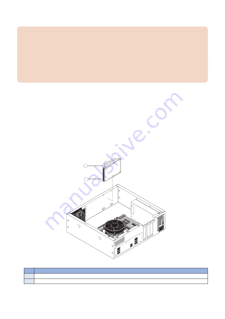
5. Remove the two screws that secure the HDD assembly to the chassis (see below figure)
Set aside the screws so that you can replace them later.
6. Carefully lift the HDD assembly to release its lower edge from the mounting posts in the chassis, and then remove the HDD
assembly from the chassis.
1
2
Figure 27: Removing the HDD assembly
No.
Item
1
Screw (1 of 2)
2
HDD assembly
3. REPLACING PARTS
36
Содержание imagePASS-P2
Страница 1: ...Revision 1 1 imagePASS P2 Service Manual ...
Страница 6: ...Introduction 1 Introduction 2 Specifications 6 ...
Страница 13: ...Using the imagePASS 2 Using the imagePASS 9 ...
Страница 16: ...Figure 3b The imagePASS Tools menu 2 Using the imagePASS 11 ...
Страница 17: ...REPLACING PARTS 3 Replacing Parts 13 ...
Страница 44: ...INSTALLING SYSTEM SOFTWARE 4 Installing System Software 40 ...
Страница 64: ...TROUBLESHOOTI NG 5 Troubleshooting 60 ...
Страница 84: ...2 Stepped Screw M4 2x 3 4x Screw with Toothed Washer M4x8 Stepped Screw M4 4 4x 8x 6 INSTALLATION PROCEDURE 79 ...
Страница 87: ...2 2x Stepped Screw M4 3 Screw with Toothed Washer M4x8 Stepped Screw M4 6x 4 4x 8x 6 INSTALLATION PROCEDURE 82 ...
Страница 88: ...5 4x Screw with Toothed Washer M4x8 6 Crossover Ethernet Cable 1x 2x 7 2x 8 2x 6 INSTALLATION PROCEDURE 83 ...


