


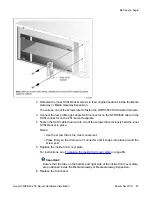
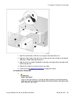


2. Refasten the inner SCSI bracket screws in their original locations inside the Media
Gateway or Media Gateway Expansion.
You will use one of the screws later to fasten the NTRH3502 SCSI cable drain wire.
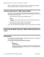
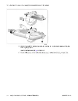
3. Connect the low profile right-angle SCSI connector on the NTRH3502 cable to the
SCSI connector on the 201i server faceplate.
4. Fasten the SCSI cable drain wire to one of the screws that previously held the inner
SCSI bracket in place.
Notes:
• Use the screw that is the most convenient.
• Press firmly on the drain wire Y-connector until it snaps into place around the
screw post.
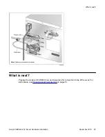
5. Replace the inside front cover plate.
For instructions, see
To replace the inside front cover plate
Important:
Ensure that the tabs on the bottom and right side of the inside front cover plate
are positioned inside the Media Gateway or Media Gateway Expansion.
6. Replace the front bezel.
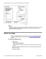
Before you begin
Avaya CallPilot
®
201i Server Hardware Installation
December 2010 87
Содержание CallPilot 201i
Страница 1: ...Avaya CallPilot 201i Server Hardware Installation 5 0 NN44200 301 01 03 December 2010 ...
Страница 8: ...8 Avaya CallPilot 201i Server Hardware Installation December 2010 ...
Страница 28: ...About the 201i server 28 Avaya CallPilot 201i Server Hardware Installation December 2010 ...
Страница 106: ...Preparing peripheral devices 106 Avaya CallPilot 201i Server Hardware Installation December 2010 ...
Страница 128: ...Connecting peripheral devices to the 201i server 128 Avaya CallPilot 201i Server Hardware Installation December 2010 ...