


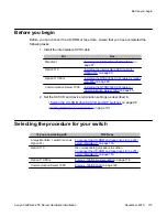


IF you are installing the 201i
server in a
THEN
the high-density connector associated with the
left slot occupied by the 201i server.
Note:
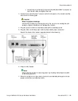
Ensure that the cable is securely fastened.
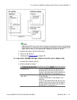
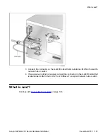
2. If you have not already done so, connect the amphenol connector drain wire as
follows:
• Option 11C or Meridian 1 to the nearest backplane grounding bolt on the switch
The following diagram shows drain wire connection on the Option 11C.
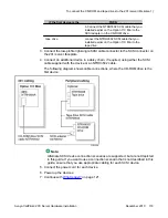
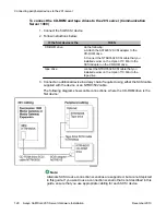
• Option 11C Mini or Communication Server 1000 to a screw on the back of the
cabinet
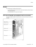
Connecting peripheral devices to the 201i server
122 Avaya CallPilot
®
201i Server Hardware Installation
December 2010
Содержание CallPilot 201i
Страница 1: ...Avaya CallPilot 201i Server Hardware Installation 5 0 NN44200 301 01 03 December 2010 ...
Страница 8: ...8 Avaya CallPilot 201i Server Hardware Installation December 2010 ...
Страница 28: ...About the 201i server 28 Avaya CallPilot 201i Server Hardware Installation December 2010 ...
Страница 106: ...Preparing peripheral devices 106 Avaya CallPilot 201i Server Hardware Installation December 2010 ...
Страница 128: ...Connecting peripheral devices to the 201i server 128 Avaya CallPilot 201i Server Hardware Installation December 2010 ...