


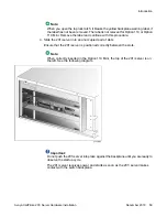


Note:
When you open the top lock latch, it breaks the yellow backplane warning label, if
the label has not been removed. The label is not relevant for Option 11C or Option
11C Mini. Remove the label and continue with this procedure.
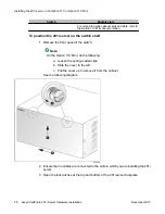
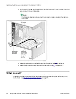
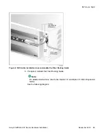
4. Slide the 201i server into an unoccupied pair of slots.
Ensure that the 201i server is positioned correctly between the slots.
Note:
When correctly inserted in the Option 11C Mini, the top of the 201i server is on
the left. See the following diagram:
Important:
Do not push the 201i server into place against the backplane until you are ready to
observe the startup cycle.
The 201i server receives power and starts as soon as the 201i server makes
contact with the switch backplane.
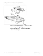
Introduction
Avaya CallPilot
®
201i Server Hardware Installation
December 2010 59
Содержание CallPilot 201i
Страница 1: ...Avaya CallPilot 201i Server Hardware Installation 5 0 NN44200 301 01 03 December 2010 ...
Страница 8: ...8 Avaya CallPilot 201i Server Hardware Installation December 2010 ...
Страница 28: ...About the 201i server 28 Avaya CallPilot 201i Server Hardware Installation December 2010 ...
Страница 106: ...Preparing peripheral devices 106 Avaya CallPilot 201i Server Hardware Installation December 2010 ...
Страница 128: ...Connecting peripheral devices to the 201i server 128 Avaya CallPilot 201i Server Hardware Installation December 2010 ...