


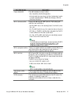


The following table describes each faceplate feature:
Faceplate feature
Description
Mouse connector
The mouse connector is a standard PS/2 connector and is hot-
pluggable.
Lock latches
Lock latches at the top and bottom of the faceplate secure the
server to the backplane of the Meridian 1 switch or the
backplane of the Communication Server 1000 Media Gateway
or Media Gateway Expansion.
Keyboard connector
The keyboard connector is a standard PS/2 connector and is
hot-pluggable.
Infrared port
For future use.
Monitor connector
The monitor connector is a standard, high-density, 15-pin
female connector.
About the 201i server
16 Avaya CallPilot
®
201i Server Hardware Installation
December 2010
Содержание CallPilot 201i
Страница 1: ...Avaya CallPilot 201i Server Hardware Installation 5 0 NN44200 301 01 03 December 2010 ...
Страница 8: ...8 Avaya CallPilot 201i Server Hardware Installation December 2010 ...
Страница 28: ...About the 201i server 28 Avaya CallPilot 201i Server Hardware Installation December 2010 ...
Страница 106: ...Preparing peripheral devices 106 Avaya CallPilot 201i Server Hardware Installation December 2010 ...
Страница 128: ...Connecting peripheral devices to the 201i server 128 Avaya CallPilot 201i Server Hardware Installation December 2010 ...