


c. Connect the 9-pin female connector to the RS-232 COM1 connector on
the multi I/O cable and tighten the nuts.
3. Connect one end of the RJ-11 phone cord to the line jack on the modem and the
other end to an analog jack.
Caution:
Risk of equipment damage
Connect the modem to an analog line only. The use of a non-analog line (for
example, digital or Multiline) can damage the modem.
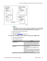
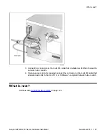
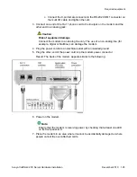
4. Plug the power cord into an electrical outlet with an isolated ground.
5. Plug the other end of the power cord into the modem power connector.
Result: The back of the modem appears similar to the following:
6. Power on the modem.
Note:
Ensure that the modem is receiving power by checking that at least one LED
on its front panel is lit.
7. Place the modem in an area where it cannot be accidentally damaged or where
people cannot trip over attached cords.
Required equipment
Avaya CallPilot
®
201i Server Hardware Installation
December 2010 125
Содержание CallPilot 201i
Страница 1: ...Avaya CallPilot 201i Server Hardware Installation 5 0 NN44200 301 01 03 December 2010 ...
Страница 8: ...8 Avaya CallPilot 201i Server Hardware Installation December 2010 ...
Страница 28: ...About the 201i server 28 Avaya CallPilot 201i Server Hardware Installation December 2010 ...
Страница 106: ...Preparing peripheral devices 106 Avaya CallPilot 201i Server Hardware Installation December 2010 ...
Страница 128: ...Connecting peripheral devices to the 201i server 128 Avaya CallPilot 201i Server Hardware Installation December 2010 ...