


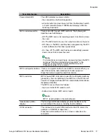


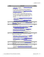


The following table identifies the purpose of each connector on the NTRH0912 multi I/O cable.
Note:
Labels on the RJ-45 cables distinguish the CLAN and ELAN connectors.
Connector type
Purpose
50-pin amphenol
This connector establishes the connection between the Meridian
1 or Communication Server 1000 Media Gateway or Media
Gateway Expansion backplane, ELAN and CLAN Ethernet hubs
or switches, and modem.
10Base-T (RJ-45)
This connector provides a 10 Mbit/s Ethernet connection
between the 201i server and the Meridian 1 switch or
Communication Server 1000 system. This connection allows the
exchange of call control information between the server and the
Meridian 1 switch or Communication Server 1000 system.
For more information about the ELAN subnet, see the CallPilot
Installation and Configuration Task List.
10/100Base-T (RJ-45)
This connector provides a network connection for
Multi I/O cable description
Avaya CallPilot
®
201i Server Hardware Installation
December 2010 23
Содержание CallPilot 201i
Страница 1: ...Avaya CallPilot 201i Server Hardware Installation 5 0 NN44200 301 01 03 December 2010 ...
Страница 8: ...8 Avaya CallPilot 201i Server Hardware Installation December 2010 ...
Страница 28: ...About the 201i server 28 Avaya CallPilot 201i Server Hardware Installation December 2010 ...
Страница 106: ...Preparing peripheral devices 106 Avaya CallPilot 201i Server Hardware Installation December 2010 ...
Страница 128: ...Connecting peripheral devices to the 201i server 128 Avaya CallPilot 201i Server Hardware Installation December 2010 ...