


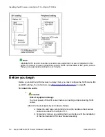


Before you begin
Before you can install the NTRH3501 cable, you must remove the existing backplane cable
from the back of the switch. See
Removing the backplane (tip and ring) cables
on page 44.
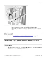
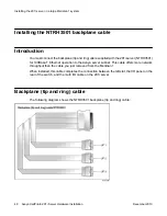
To install the NTRH3501 backplane cable
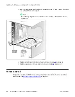
Install and connect the NTRH3501 cable to the multi I/O cable as follows:
a. Attach the backplane connector of the NTRH3501 cable to the inside of the
I/O panel slot associated with the 201i server left slot.
Insert the original screw into the tie wrap base and fasten the screw into the
lower position of the I/O panel slot.
b. Attach the three inner cables to the backplane connectors associated with
the left slot as follows:
• UP 1 cable to the top position
• UP 2 cable to the middle position
• UP 3 cable to the lower position
Important:
The connectors are keyed; you can insert them in one position only.
Use tie wraps to secure the cables in their original positions.
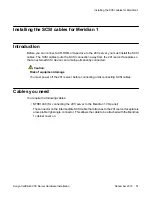
c. Connect the 50-pin amphenol connector on the multi I/O cable (NTRH0912)
to the NTRH3501 backplane cable connector on the I/O panel.
See the following diagram:
Before you begin
Avaya CallPilot
®
201i Server Hardware Installation
December 2010 49
Содержание CallPilot 201i
Страница 1: ...Avaya CallPilot 201i Server Hardware Installation 5 0 NN44200 301 01 03 December 2010 ...
Страница 8: ...8 Avaya CallPilot 201i Server Hardware Installation December 2010 ...
Страница 28: ...About the 201i server 28 Avaya CallPilot 201i Server Hardware Installation December 2010 ...
Страница 106: ...Preparing peripheral devices 106 Avaya CallPilot 201i Server Hardware Installation December 2010 ...
Страница 128: ...Connecting peripheral devices to the 201i server 128 Avaya CallPilot 201i Server Hardware Installation December 2010 ...