

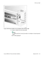


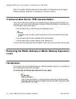

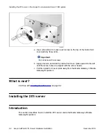
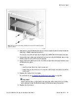

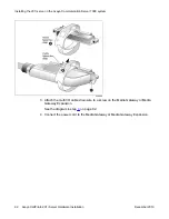


Remove the front bezel from the Media Gateway or Media Gateway Expansion as
shown in the diagram on the next page.
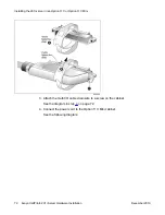
a. Use a slot screwdriver to gently pry off the label.
b. Insert the screwdriver approximately 2 cm (0.75 in.) into the open slot,
and then gently lift the screwdriver handle, thus applying downward
pressure on the tab inside the bezel.
At the same time, gently pull the bezel away from the chassis
(approximately 2 cm [0.75 in.]) until the inside tab has cleared the catch.
c. Grasp the bezel by both sides and carefully pull it straight away from the
Media Gateway or Media Gateway Expansion.
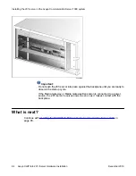
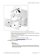
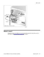
2. Remove the inside front cover plate as follows:
Introduction
Avaya CallPilot
®
201i Server Hardware Installation
December 2010 81
Содержание CallPilot 201i
Страница 1: ...Avaya CallPilot 201i Server Hardware Installation 5 0 NN44200 301 01 03 December 2010 ...
Страница 8: ...8 Avaya CallPilot 201i Server Hardware Installation December 2010 ...
Страница 28: ...About the 201i server 28 Avaya CallPilot 201i Server Hardware Installation December 2010 ...
Страница 106: ...Preparing peripheral devices 106 Avaya CallPilot 201i Server Hardware Installation December 2010 ...
Страница 128: ...Connecting peripheral devices to the 201i server 128 Avaya CallPilot 201i Server Hardware Installation December 2010 ...