background image

Downloading a CFIG File to the Panel,

 Continued

11-6

Step 4. Start Download at 
PC, 

continued

3.

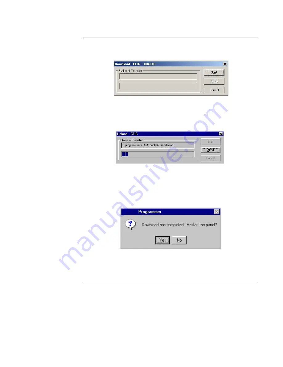
Click OK.  The dialog shown in Figure 11-8 appears, prompting you to begin the 
download.

Figure 11-9.  Download Dialog

4.

Click on the Start button to begin the download.  A progress thermometer appears, 
tracking the progress of the download.

Figure 11-10.  Transfer in Progress Screen

Note:  You must restart the panel from the PC, not the panel.  Pressing the panel’s warm start 
button causes all downloaded information to be lost.

Figure 11-11.  Restart Panel Prompt


Содержание AutoPulse Z-28

Страница 1: ...PC PROGRAMMING INSTRUCTIONS AGENT RELEASE CONTROL SYSTEM ANSUL 28 P N 579 383 Doc 430546 12 3 02 Rev A...

Страница 2: ......

Страница 3: ...NSTRUCTIONS Follow the instructions in the installation operating and programming manuals These instructions must be followed to avoid damage to the control panel and associated equipment Fire Alarm C...

Страница 4: ...ification appliance s Auxiliary formerly NFPA 72B Requires City Circuit Module Part No 430607 Remote Station protected premise formerly NFPA 72C Requires City Circuit Module Part No 430607 UL 864 List...

Страница 5: ...Water Spray Systems NFPA 16A Standard for the Installation of Closed Head Foam Water Sprinkler Systems NFPA 17 Standard for Dry Chemical Extinguishing Systems NFPA 17A Standard for Wet Chemical Exting...

Страница 6: ...panel key located below the display is referenced in this manual it is normally shown between left and right arrows Examples are ALARM SILENCE and SYSTEM RESET Numbered lists indicate procedures with...

Страница 7: ...Step 2 Install or Upgrade the PC Programmer Software 2 4 Overview 2 4 Procedure 2 4 Chapter 3 Downloading a BIN File 3 1 Introduction 3 1 Before You Begin 3 1 In This Chapter 3 1 Connecting Serial Ca...

Страница 8: ...200 4 7 Step 2 Connect Serial Cable between PC and Panel 4 8 Step 3 Enable Upload on Panel 4 9 Step 4 Start Upload at PC 4 10 Saving Archiving Backing Up and Restoring Jobs 4 12 Overview 4 12 Saving a...

Страница 9: ...Custom Labels 6 11 Programming the AUX Relay Card 6 12 Overview 6 12 Step 1 Open the AUX Relay Card 6 12 Step 2 Edit the Point Type 6 13 Step 3 Edit Custom Label 6 14 Programming the SLCnet Card 6 15...

Страница 10: ...ramming Events 6 38 Chapter 7 Programming Points 7 1 Introduction 7 1 In This Chapter 7 1 Overview Point Tab 7 2 Overview 7 2 Splitter Bar 7 2 Site Card and Point Views 7 2 Sort Order 7 2 Word Library...

Страница 11: ...e User Program 10 6 Procedure 10 6 Step 2 Add Additional Inputs and Outputs to an Equation 10 7 Overview 10 7 Adding Additional Inputs 10 7 Adding Additional Outputs 10 7 Step 3 Edit An Input Statemen...

Страница 12: ...AHUO A 3 AHUR A 3 BSIGNAL A 4 DHOLDER A 4 PRIMARY A 4 SQALERT A 5 RELAY A 5 RELISIG A 5 RELSIG A 5 RELVIS A 6 RELWVIS A 6 RSIGNAL A 6 RVISUAL A 6 SIGNAL A 7 SSIGNAL A 7 SUPREL A 7 SVISUAL A 8 SWATER...

Страница 13: ...igital Pseudo Points A 25 AUTOPULSE Z 28 User Digital Pseudos A 29 Analog Pseudo Points A 29 AUTOPULSE Z 28 System Analog Pseudos A 29 AUTOPULSE Z 28 User Analog Pseudos A 30 List Pseudo Points A 31 A...

Страница 14: ...Apply to ALL Hazard Areas Checkbox C 6 Dual Detector Operation C 6 Timer Configurations C 7 Abort Logic C 7 Searching Hazard Areas C 8 Deleting Items C 8 Renaming Hazard Areas C 8 Index I 1...

Страница 15: ...s to provide additional outputs and additional power Additionally the AUTOPULSE Z 28 can automatically control supplementary equipment such as fire doors and fans during an alarm condition using its a...

Страница 16: ...1 1 Related Documentation Doc Number Title 430544 AUTOPULSE Z 28 Installation Operation and Front Panel Pro gramming Instructions 431308 NACext Installation instructions 431309 NAC Option Card Part N...

Страница 17: ...ttributes Figure 1 1 shows the location of the tabs Refer to Tabs later in this section for specific information Icons that allow you to quickly perform routine tasks such as printing saving a job etc...

Страница 18: ...that represent the building components floors offices hallways etc to the site tree and associating points with the correct label For example if the site tree contains a label named LOBBY you would a...

Страница 19: ...of the options contained in the menu structure are not available elsewhere in the application i e there is no icon or tab for Preferences Figure 1 3 Programmer Menu Structure File Menu View Menu Edit...

Страница 20: ......

Страница 21: ...on 3 x programmer software on your PC Once you have done this you must download the BIN file from the distribution floppy disk to the panel Refer to Chapter 3 for information on downloading the Versio...

Страница 22: ...software Mouse with at least two buttons 16 Mb RAM 32Mb recommended 850 Mb or greater hard drive Required Components Other components that you may need include Software key Ansul Part 742 079 Downloa...

Страница 23: ...g that there is either a missing or incorrect key and the Panel Programmer will terminate with no further action Installation Use the following procedure to install the key 1 Turn OFF power to your co...

Страница 24: ...after approximately 10 to 20 seconds Figure 2 2 Installation Welcome Screen 2 Click Next The screen shown in Figure 2 3 appears The default installation directory is C Program Files Panel Programmer P...

Страница 25: ...r appears indicating the progress of the file copy operation The next prompt shown in Figure 2 4 indicates that the installation is finished If there is a previous version of the programmer on the PC...

Страница 26: ......

Страница 27: ...Z 28 FACP are made and additional copies of the BIN file become available Before You Begin Before getting started make sure that you have the following Download cable Ansul Part 431206 Floppy with Ve...

Страница 28: ...e service port of the AUTOPULSE Z 28 FACP as follows 1 Locate the PC within 6 feet of the AUTOPULSE Z 28 FACP and connect the end shown in Figure 3 1 to the PC Make sure that the red stripe is aligned...

Страница 29: ...ection Figure 3 2 Serial Port Settings Step 3 Set AUTOPULSE Z 28 FACP Baud Rate Switches 2 1 and 2 2 on the AUTOPULSE Z 28 FACP set the panel s baud rate Table 3 1 summarizes the possible settings for...

Страница 30: ...lar to the following appears Figure 3 5 Initialize Upload Download Option 5 Press the NEXT or PREV keys until Initialize Up Dwnload is displayed and press ENTER The AUTOPULSE Z 28 displays the followi...

Страница 31: ...the PC Programmer s hard drive It is recommended that you copy the file to the following directory This is the default directory in which the programmer looks for BIN files PROGRAM FILES PANEL PROGRA...

Страница 32: ...Figure 3 9 Open Dialog 5 Select the directory to which the file was copied click on the name of the EXEC file and then select the Open button A dialog similar to the following displays Figure 3 10 Do...

Страница 33: ...EXT until PANEL RESTART is displayed Figure 3 11 Panel Restart Option 4 Press ENTER A screen similar to the following appears Figure 3 12 Warm Start Option 5 Press the NEXT or PREV keys until Warm Sta...

Страница 34: ......

Страница 35: ...ading a job from the panel Saving archiving backing up and restoring jobs In This Chapter Refer to the following pages for specific information on a topic Topic See Page Using Quick CFIG to Autoconfig...

Страница 36: ...TRELAY Remote annunciators are detected at their set address Hardware that is not automatically configured includes Graphic annunciators Suppression points Quick CFIG Reconfigure All Hardware Option T...

Страница 37: ...ther which indicates that Quick CFIG is scanning for SLCnet devices The Reconfigure ALL Hardware function is complete when a message similar to the following appears Figure 4 4 Hardware Detection Comp...

Страница 38: ...g the Start Menu Click on the Start menu and point to Programs When the choices appear point to Panel Programmer and then choose Programmer A screen similar to the one shown in Figure 4 5 appears Figu...

Страница 39: ...TANT It is strongly recommended that each job be archived and backed up for future reference Note Network system options are not available and are grayed on the New System dialog Step 1 Invoke New Sys...

Страница 40: ...rogramming See the next section for details Procedure 1 Click on the File menu 2 Select Open A window similar to the following appears Figure 4 7 Open Database Dialog 3 Open the folder containing the...

Страница 41: ...d the job but you cannot edit the job s attributes i e change system options add points etc Step 1 Set Panel and PC Baud Rates to 19 200 1 Set switches SW1 and SW2 to the positions shown in Figure 4 8...

Страница 42: ...to 8 Step 2 Connect Serial Cable between PC and Panel Connect a serial cable Part No 431206 between a free serial port on the service PC and the service port of the AUTOPULSE Z 28 FACP 1 Locate the PC...

Страница 43: ...re 4 12 Initialize Up Download Option 5 Press the NEXT or PREV keys until Initialize Up Dwnload is displayed and press ENTER The AUTOPULSE Z 28 displays the following message to indicate that the pane...

Страница 44: ...button to begin the upload One of the following occurs depending on whether a job by the same name already exists in the PC s APJOBS folder If Job Name Already Exists on PC If a job by the same name...

Страница 45: ...re 4 16 Transfer in Progress The following message appears when the upload is complete Figure 4 17 Upload Complete Message 4 Click OK to continue The next message indicates that the programmer is unbu...

Страница 46: ...ersion of the job using the job name specified by the user followed by the MDB file extension to the PC s hard disk To save a job do the following 1 Open the Save dialog in either of the following way...

Страница 47: ...copy of a job and does the following with it Archiving a Job Saves the job to floppy or a remote networked disk Saves the job to the hard disk marking it Read Only This copy can be restored at a late...

Страница 48: ...if necessary 7 Click OK Figure 4 23 Archive Complete Notification 8 When the Programmer Archive Utility dialog reappears click Exit to close the Archive utility Backing Up a Job Backup stores a read w...

Страница 49: ...d Up or Archived Job Restore allows previously backed up or archived jobs to be retrieved for viewing or editing To restore a backed up or archived job follow these steps 1 Click on the File menu and...

Страница 50: ...extension A prompt similar to the following appears Figure 4 26 Select Drive Prompt 4 Select the drive letter and click OK A message similar to the following appears Figure 4 27 Restore Prompt 5 Clic...

Страница 51: ...s chapter describes setting the system s general information system options passcodes and access levels In This Chapter Refer to the following pages for specific information on a topic Topic See Page...

Страница 52: ...nter general information 1 Select the Panel tab 2 Make sure the General Information radio button is selected A window similar to the following appears Figure 5 1 General Information Screen 3 Enter the...

Страница 53: ...ormat option allows you to display system time in 12 or 24 hour format That is time is displayed in either a 12 hour format that uses an AM morning or PM afternoon designation or in 24 hour military s...

Страница 54: ...nd a depleted battery condition occurs the NACs are prevented from activating Canadian Operation The default setting for the option is OFF and the depleted battery threshold voltage is 19 4 VDC 5 Oper...

Страница 55: ...tion has expired the AUTOPULSE Z 28 shuts off the door holder relays and the doors close The range for the timer is 0 60 seconds with a default setting of zero seconds To have door holders drop the do...

Страница 56: ...Figure 5 9 AHU Stagger Start Option Active Status Reminder The Active Status Reminder option allows you to set an interval and duration during which the AUTOPULSE Z 28 reminds operators that a FIRE SU...

Страница 57: ...ext page Table 5 1 Signal Choices Signal Type Choices Audible NAC Operation Temporal A three pulse coding pattern consisting of three second pulses each separated by second silence Each group of three...

Страница 58: ...duce network initialization time and network traffic This option should not be selected if any Custom Control is written against non threshold value changes of LIFEalarm points or if current values ar...

Страница 59: ...ccess Levels and Operations Access Level Operations 1 Ack Silence System Reset 2 Default Passode 2000 All Level 1 operations plus Set Time Date Point Control Enable Disable Points 3 Default Passode 30...

Страница 60: ...adio button See Figure 5 14 3 Edit the passcodes as necessary Figure 5 15 Passcodes Setting Access Levels 1 Select the Panel tab if it is not already selected 2 Click on the Access Levels radio button...

Страница 61: ...on on a topic Topic See Page Overview Card Tab 6 2 Adding Deleting Cards 6 4 Programming the Master Controller SFI O Card 6 5 Programming the NAC Card 6 9 Programming the AUX Relay Card 6 12 Programmi...

Страница 62: ...represents all Digital User Pseudo Points Available Card List The right hand side of the screen lists available option cards that can be added to the system Splitter Bar The width of the Active Card a...

Страница 63: ...oints If the points do not adjoin one another hold down the CTRL key and select each point Release the CTRL key only after all points have been selected 4 Press the F4 key The AutoFill dialog appears...

Страница 64: ...ilable Cards List select the card you want to add 2 Hold the left mouse button down drag the card to the Active Card List and release the mouse button The programmer prevents you from adding cards tha...

Страница 65: ...SFI O Card Programming Screen Programming User Defined LEDs Each user defined LED allows you to monitor the state of a specific system point illuminating when the state of the point changes For examp...

Страница 66: ...udo Continued on next page point and illuminates the Yellow LED if P76 turns ON Table 6 1 Modes for User Defined LEDs Mode Meaning Disable LED illuminates when the state of the REF ADDR point is DISAB...

Страница 67: ...ed 2 Click on the Mode drop down list box and select ON 3 Click on the Ref Address list box and select P76 The SMPL equation for the Earth Ground Detect example is shown below INPUT ON CODE 2 2 or ON...

Страница 68: ...e local panel LTACK Function key acknowledges all trouble events LTEST Function key performs a lamp test ONOFF N A with user defined function keys PBH Pressing the function key turns the specified poi...

Страница 69: ...elow Figure 6 5 NAC Card Location within Active Cards List Step 1 Open the NAC Card Double click on the NAC icon shown in Figure 6 6 A window similar to the following appears This window displays all...

Страница 70: ...elay ALTERN Elevator capture alternate BSIGNAL Trouble supervisory bell signal DHOLDER Door holder control PRIMARY Elevator capture primary QALERT NACnet Non Addressable signal RELAY Generic relay REL...

Страница 71: ...as follows 1 Move to the line corresponding to the NAC whose custom label you want to change 2 Double click on the NAC s existing label and type the appropriate label Refer to Using AutoFill at the b...

Страница 72: ...represents all AUX relays as the AUX Relay card Opening this card allows you to view and program the point type and custom label for these relays Note AUX Relays do not have a programmable device typ...

Страница 73: ...n relay dual relay control AHUR AHU on off relay signal relay ALTERN Elevator capture alternate BSIGNAL Trouble supervisory bell signal DHOLDER Door holder control PRIMARY Elevator capture primary QAL...

Страница 74: ...as follows 1 Move to the line corresponding to the AUX Relay whose custom label you want to change 2 Double click on the relay s custom label field and enter the appropriate label Refer to Using Auto...

Страница 75: ...m the device type point type custom label and mode sounder base smoke detectors only for each SLCnet point Figure 6 8 shows the location of the SLCnet card within the Active Card List Figure 6 9 SLCne...

Страница 76: ...olator base KACPULL KAC Pull Station MAZAM Class A Monitor ZAM T sense MBZAM Class B Monitor ZAM T sense OHEAT LIFEalarm Heat Detector with ROR PHOTO LIFEalarm Photoelectric Detector QIPHOTO Quick Con...

Страница 77: ...uppression release point you must use the front panel programmer Step 4 Set Single Station Mode Detectors with Sounder Bases Only LIFEalarm devices with sounder bases default to Single Station mode Si...

Страница 78: ...nalog Pseudo Cards Viewing Card 18 Digital System Pseudos Card 18 represents the Digital System Pseudos These points store a value of ON or OFF and are used by the system to monitor and control system...

Страница 79: ...Custom Label for each user defined digital pseudo point follow these steps 1 Double click on the Card 19 icon within the Active Cards List A window similar to the following appears Figure 6 13 Card 19...

Страница 80: ...er to Continued on next page Figure 6 14 for an example of this screen Table 6 6 Point Types for User Defined Digital Pseudo Points Point Type Application ALARM Turning ON a digital pseudo point with...

Страница 81: ...r Pseudos store analog values that can be used in Custom Control equations The exact function of an analog user pseudo depends on its point type counter timer or analog value Double clicking on the Ca...

Страница 82: ...a means of monitoring a range of similar devices All Waterflow Alarm Monitor Zones for example Double clicking on the Card 22 icon within the Active Cards List displays the System List Pseudo points a...

Страница 83: ...point turns ON if one of the points referenced in the list turns ON You can only edit a list s custom label from the Card Tab Follow the steps below to program a user defined list pseudo s custom lab...

Страница 84: ...reen Step 2 Configure Communication Settings Configure the settings for the printer attached to Port A or Port B as follows 1 Click on the Port A or Port B radio button 2 Click on the drop down list b...

Страница 85: ...screen Table 6 9 Event Choices Checkbox Application Fire Alarm Events Prints an event when an ALARM condition occurs Trouble Events Prints an event when a TROUBLE condition occurs Supervisory Events...

Страница 86: ...or control the Z 28 FACP Step 1 Open the RS 232 Service Modem Card Screen Double click on the icon that represents the RS 232 Service Modem card If the card is not already in the Active Cards List you...

Страница 87: ...that you must type For example to use the TIME command you need to type at a minimum the T Continued on next page character In the examples the character represents the prompt Table 6 10 Event Choice...

Страница 88: ...NT S ET Allows the user to manipulate the status of a control point or digital pseudo point Turning a Point ON Enter the SET command followed by the point s address see Appendix A for a list of point...

Страница 89: ...or Supervisory List Enter the ACK command followed by F T or S For example ACK F LOG IN Logging in to a Remote System Enter LOGIN at the prompt and wait for the prompt to reappear When it does enter...

Страница 90: ...s the supervisory log CLOG Prints the combined log TASERV Prints a LIFEalarm service report TASTAT Prints a LIFEalarm status report DIS ABLE Allows the user to disable enable points Disabling a Point...

Страница 91: ...he Device Type field and select GRAPHIN device type 2 Click on the point type field and select one of the following OSWITCH Specifies a two position switch supervised for open circuits Requires an EOL...

Страница 92: ...nables the referenced point Normal Disables the referenced point OSWITCH Short Enables the referenced point Normal Disables the referenced point SSWITCH Limited Enables the referenced point Normal Dis...

Страница 93: ...ON and holds it ON Normal Mode OFF OSWITCH Short Turns point ON and holds it ON Normal Mode OFF SSWITCH Limited Turns point ON and holds it ON Normal Mode OFF TSWITCH Normal Mode OFF Short Turns point...

Страница 94: ...f point Normal Mode OFF SSWITCH Limited Toggles the disable enable state of point Normal Mode OFF TSWITCH Normal Mode OFF Short Toggles the disable enable state of point Limited Toggles the disable en...

Страница 95: ...ecific information on the modes 4 Click on the Ref Addr field and select the point used to trigger the output Table 6 13 Output Device Modes Mode Application DISABLE Output activates when the referenc...

Страница 96: ...to monitor the state of specific points Step 1 Open the LCD Annunciator Card Screen Double click on the card icon that represents the annunciator A screen similar to the following appears The names o...

Страница 97: ...t Types LED 1 Select Yellow for a Yellow LED Select Non Yellow for a Red LED LED 2 Select Yellow for a Yellow LED Select Non Yellow for a Red LED LED 3 Select Yellow for a Yellow LED Select Non Yellow...

Страница 98: ...either physical points pseudo points list points or no entries Programming Events The Event Reporting panel of the LCD Annunciator card programming screen allows you to select which events are report...

Страница 99: ...each point s device type point type and custom label In This Chapter Refer to the following pages for specific information on a topic Topic See Page Overview Point Tab 7 2 Programming a Point s Hardwa...

Страница 100: ...g radio button in the View panel top right Figure 7 1 Site View uses the site tree to display the points Card View breaks down the points by card listing each card s points beneath an icon that repres...

Страница 101: ...he selected points Custom Label Spell Check Spell check allows you to validate the spelling of custom labels and can be used to check either selected points or all points 1 Make sure Point View is sel...

Страница 102: ...by the following dialog Figure 7 2 Spell Check Correction Dialog 4 Choose an option as follows Change Changes spelling of the highlighted word to the suggestion Ignore Treats the word as correct for t...

Страница 103: ...ce type that is appropriate for the point being programmed Refer to Table 7 1 for quick reference information or refer to Appendix A for detailed information on the hardware device types Continued on...

Страница 104: ...h 4 NACs AUTOPULSE Z 28 ExtA8 AUTOPULSE Z 28 ExtA with 8 NACs RAUTOPULSE Z 28 ExtA AUTOPULSE Z 28 ExtA 4 NAC s with Repeater RAUTOPULSE Z 28 ExtA8 AUTOPULSE Z 28 ExtA 8 NAC s with Repeater ADRPUL Addr...

Страница 105: ...Heat Detector with sounder SION Ion Detector with sounder SOHEAT Heat Detector with ROR and Sounder SPHOTO Photo with sounder XIPHOTO Extra sensitive Photo ISO XPHOTO Extra sensitive Photo XRPHOTO Ex...

Страница 106: ...st this with what happens when a Current Limited condition occurs for a device associated with the SO point type In this case an abnormal physical state exists To have actions occur as a result of the...

Страница 107: ...isory Duct Detector SFIRE Combination Smoke Fire Zone SFPUMP Supervisory Fire Pump Monitor SGENMON Supervisory Generator Monitor SMOKE Smoke detector SO Sprinkler supervisory normally open SPULL Combi...

Страница 108: ...elease off on silence RELVIS Suppression release visual signal on when releasing output activates off on reset RELWVIS Releasing warning visual circuit on when alarm occurs in hazard area off on reset...

Страница 109: ...the point whose label you want to program 2 Move to the point s Custom Label field and double click with the left mouse button A flashing cursor appears indicating that you should enter text 3 Edit t...

Страница 110: ......

Страница 111: ...chapter describes editing the name of a list and adding or deleting points from a list In This Chapter Refer to the following pages for specific information on a topic Topic See Page Overview List Ta...

Страница 112: ...are not auto generated Lists 8 through 12 These are lists containing suppression release points not used List 13 contains Class A ZAM Reset points and is not auto generated Lists 26 through 50 are ava...

Страница 113: ...l Site View shows a list of the points grouped by site information Card View organizes the points according to which card they are associated with Point View is the default view It displays a numerica...

Страница 114: ...how it is selected When all points have been selected release the CTRL key 2 Hold down the left mouse button and drag the points into the list area While continuing to hold down the mouse button posit...

Страница 115: ...pter describes creating a site tree which is a tree like representation of your building and its fire alarm points In This Chapter Refer to the following pages for specific information on a topic Topi...

Страница 116: ...re 9 1 shows a typical site tree Figure 9 1 Typical Site Tree Terms and Concepts Important terms and concepts related to a site tree include Book icons represents element of the tree that contain subo...

Страница 117: ...eas leaf indicates that the new element is subordinate to the highlighted element In Figure 9 1 for example the highlight is on OFFICE 2 Inserting a Level would add an element equal to OFFICE 2 Insert...

Страница 118: ...button in the View panel Site view shows a list of the points grouped by the Site information Card View organizes the points according to which card they are associated with Point View is the default...

Страница 119: ...acters or less 3 To add an additional building right click on the entry that you just added the building and select Insert Level Insert Level adds an element to the tree that is equal to the currently...

Страница 120: ...right of the highlighted floor 3 Double click on Leaf Enter a name for the floor in the text entry box The name must be 10 characters or less Repeat these steps choosing different floors as required...

Страница 121: ...trol equations In This Chapter Refer to the following pages for specific information on a topic Topic See Page Overview CC Tab 10 2 Overview Components of a CC Equation 10 4 Step 1 Add a New Equation...

Страница 122: ...and equations appear on the left side of the window Figure 10 1 CC Tab Use the View button shown at the top of the points list to change filter and sort the way in which points are displayed in the li...

Страница 123: ...e associated with Point View is the default view It displays a numerical list of all points b Choose Ascending or Descending order Ascending order lists the points from highest number to lowest and de...

Страница 124: ...t Perform a function such as Delay Cycle Compare two values or Save Recall values Multiple input statements located within the same equation must be separated by a logical operator AND or OR These ope...

Страница 125: ...below IF the condition of M1 1 is Fire OR the condition of M1 2 is Fire then the INPUT SIDE is true In other words when the status of either M1 1 or M1 2 becomes Fire the output statements execute Fig...

Страница 126: ...represented by an icon on the left side of the screen Follow these steps to add a new equation to the User Program 1 Right click on the User icon See Figure 10 6 for its location 2 Highlight Add Equa...

Страница 127: ...click on the sign to expand the equation Adding Additional Inputs 1 Highlight one of the equation s existing input statements and click the right mouse button 2 Click on Add Input An additional input...

Страница 128: ...the right mouse button A menu of choices appears 2 Click on Properties A dialog similar to Figure 10 7 appears Figure 10 7 Custom Control Input Dialog 3 Use the AND OR logical operators to specify whe...

Страница 129: ...qualifiers Associating Points with Input Statements After defining the Opcode and Qualifier for an input statement you need to associate a point with the statement To do this follow these steps 1 In t...

Страница 130: ...input condition is TRUE until the trouble condition is acknowledged Supervisory When the referenced point enters a supervisory condition the input condition is TRUE until the problem condition is fix...

Страница 131: ...Trouble The input condition is TRUE when the state of the referenced point is a Class A Trouble ON Coding The input condition is TRUE when a signal circuit NAC or relay is ON or coding i e sounding f...

Страница 132: ...dition the input condition is TRUE until the problem condition is fixed ALL Opcode All devices within the list must enter an supervisory condition for the input condition to be TRUE If this occurs the...

Страница 133: ...output side of the equation can be used to pressurize only the floor s with detectors in this state and ignore any pull stations that may have been pulled and may or may not be on the fire floor ALL...

Страница 134: ...trolled from the panel All Opcode The input is TRUE if all points within the list have been manually overridden i e controlled from the panel Delay Constant Allows the Custom Control input condition t...

Страница 135: ...nd its result stored in a register as a 1 true or 0 false There are six registers available for use RECALL Allows an input to recall the value of a register and use it beside other input conditions If...

Страница 136: ...renced extra sensitive photo smoke detector exceeds 0 2 Smoke level 0 5 Input statement is TRUE when the smoke level for the referenced extra sensitive photo smoke detector exceeds 0 5 Smoke level 1 0...

Страница 137: ...ng appears Figure 10 9 Custom Control Output Dialog 3 Use Table 10 2 to set the Opcode and Qualifier Continued on next page Table 10 2 Output Opcodes and Qualifiers Opcode Qualifier Application Hold O...

Страница 138: ...PRI When the input side of the equation is true the priority is changed to a value that you specify When the input is false the priority returns to its original value Set On When the input side of the...

Страница 139: ...door holders etc Fast March Time When the input side of the equation is true all devices on the SLCnet channel turn on and off in fast march time Temporal When the input side of the equation is true a...

Страница 140: ...When the input side of the equation is true the threshold level for the ION smoke detector is set to 1 3 Smoke Level 1 7 When the input side of the equation is true the threshold level for the ION sm...

Страница 141: ...Qualifier for an output statement you need to associate a point with the statement To do this follow these steps 1 In the list on the right side of the screen click on the name of the point 2 Hold do...

Страница 142: ......

Страница 143: ...This chapter describes building an AUTOPULSE Z 28 job and downloading it to the AUTOPULSE Z 28 panel In This Chapter Refer to the following pages for specific information on a topic Topic See Page Bu...

Страница 144: ...der utility does the following Automatically saves the job being built Verifies that the hardware and the configured points are accurate Produces the CFIG file To build a job follow these steps 1 Clic...

Страница 145: ...baud rate of 19 200 on the AUTOPULSE Z 28 FACP Figure 11 2 Switch Position for 19 200 Baud 2 Start the AUTOPULSE Z 28 Programmer application Click on the Transfer menu and select Settings A dialog sim...

Страница 146: ...gure 11 4 to the PC 2 Connect the other end to the service port on the AUTOPULSE Z 28 FACP Make sure that the red stripe is aligned to the left as you connect the cable Figure 11 4 Connecting Serial C...

Страница 147: ...dicate that the panel is ready to accept a download Figure 11 7 File Transfer Initialized Notification Step 4 Start Download at PC 1 Click on the Transfer menu When the selections appear choose Transf...

Страница 148: ...wnload Figure 11 9 Download Dialog 4 Click on the Start button to begin the download A progress thermometer appears tracking the progress of the download Figure 11 10 Transfer in Progress Screen Note...

Страница 149: ...smoke detectors pull stations heat detectors fire pump monitors etc Control point types are used with signal notification appliance and relay devices Point Addresses and definitions Each AUTOPULSE Z...

Страница 150: ...1 Sensor Base Device Types Standard Base 430636 LED Base 430637 Sounder Base Isolator Base 430640 External Duct Base 430649 430650 Relay Base 430638 Photo Sensor PHOTO XPHOTO SPHOTO XSPHOTO IPHOTO XI...

Страница 151: ...you have a single relay that performs both ON and OFF functions see AHUR AHUR AHU on off relay single relay control This point type is used with applications in which a single relay performs AHU ON a...

Страница 152: ...recall By default these relays pick on any alarm Continued on next page Circuit Status LCD Display System Status ON ALT Elevator Recall ON OFF ALT Elevator Recall OFF ALT Elevator Recall CODING Disab...

Страница 153: ...vestigate timer expires Note If RELISIG is assigned to a point that is not configured for NYC abort the RELISIG point will have No Operation RELSIG Suppression release audible signal Uses programmed c...

Страница 154: ...ormed Points assigned with this type operate on general alarm Continued on next page Circuit Status LCD Display System Status ON Release Visual ON OFF Release Visual OFF Release Visual CODING Disabled...

Страница 155: ...n release output Continued on next page Circuit Status LCD Display System Status ON Signal Circuit ON OFF Signal Circuit OFF Signal Circuit CODING Disabled TBL Signal Circuit TROUBLE OFF AUTO TBL Visu...

Страница 156: ...ctivated until the Alarm Silence key is pressed TSIGNAL Trouble supervisory signal Circuit Status LCD Display System Status Normal Signal Circuit ON Normal Signal Circuit OFF Signal Circuit CODING Dis...

Страница 157: ...peration of a duct detector for all possible circuit states HEAT Used to define the operation of a heat detector for all possible circuit states Continued on next page Circuit Status LCD Display Syste...

Страница 158: ...anel Continued on next page Circuit Status LCD Display System Status Normal Normal Limited Flame Detector Fire Alarm Open Flame Detector Open Trouble Short Flame Detector Fire Alarm Circuit Status LCD...

Страница 159: ...next page Circuit Status LCD Display System Status Normal Normal Limited Fire Monitor Zone Smoke Alarm Open Fire Monitor Zone Open Trouble Short Fire Monitor Zone Fire Alarm Circuit Status LCD Display...

Страница 160: ...s abnormal The current limited condition indicates that the fire pump is running SFPUMP Same as the FPUMP point type except that the fire pump running condition requires operator acknowledgment Contin...

Страница 161: ...stor Refer to the AUTOPULSE Z 28 field wiring diagrams A short condition indicates waterflow alarms SUPDET Suppression Agent Discharge monitor Continued on next page Circuit Status LCD Display System...

Страница 162: ...pen Trouble Short Suppression Abort Short Trouble Circuit Status LCD Display System Status Normal Normal Limited Suppression Manual Dump Activated Open Suppression Manual Dump Open Trouble Short Suppr...

Страница 163: ...rmal Normal Limited Trouble Monitor Abnormal Open Trouble Monitor Open Trouble Short Trouble Monitor Abnormal Circuit Status LCD Display System Status Normal Normal Limited Smoke Detector Verified Ala...

Страница 164: ...Detector Abnormal Circuit Status LCD Display System Status Normal Normal Limited Fire Alarm Abort Abnormal Open Fire Alarm Abort Open Trouble Short Fire Alarm Abort Abnormal Circuit Status LCD Display...

Страница 165: ...sition Switch Invalid State TBL Open 2 Position Switch ON Disable TBL 2 Position Switch Disable TBL Circuit Status LCD Display System Status Normal OFF Limited 2 Position Switch Invalid State TBL Open...

Страница 166: ...ates the status of the piezo sounder on the AUTOPULSE Z 28 Master 0 2 R External N2 Disconnect Relay Indicates the status of the External N2 Disconnect Relay Turns on when no slaves are communicating...

Страница 167: ...Points Point Type Label default Description 1 1 U NAC Circuit SIG 1 NAC card Signal 1 status and configuration 1 2 U NAC Circuit SIG 2 NAC card Signal 2 status and configuration 1 3 U NAC Circuit SIG...

Страница 168: ...trouble Only occurs if expansion supply is configured 2 6 Battery Low This trouble point indicates that the battery has a voltage less than 22 8 V 2 7 Battery Depleted Disconnected This trouble point...

Страница 169: ...O card are default labels and cannot be changed by the user The following table describes the organization of points on the 24 I O card In this table card represents the card address 9 14 of the 24 I...

Страница 170: ...tA Card may vary depending on the number of AUTOPULSE Z 28 ExtA devices configured in the system The AUTOPULSE Z 28 can have up to five AUTOPULSE Z 28 ExtA devices programmed into the system with each...

Страница 171: ...rst AUTOPULSE Z 28 ExtA device configured in the system The device is indicated by the SLCnet address provided 17 2 U SLCnet M1 AUTOPULS E Z 28 ExtA NAC 2 The status of the second NAC on the first AUT...

Страница 172: ...SLCnet M1 AUTOPULSE Z 28 ExtA NAC 3 The status of the third NAC on the fifth AUTOPULSE Z 28 ExtA device configured in the system The device is indicated by the SLCnet address provided 17 36 U SLCnet M...

Страница 173: ...nts which may be programmed as follows Each system digital pseudo point falls into one of the following categories The system digital pseudo card in the AUTOPULSE Z 28 system is located at address 18...

Страница 174: ...SMPL Program On when User SMPL program is active D7 R T Cold Start Indicates that panel has performed a cold start Turns of when acknowledged D8 R T Warm Start Check Time and Date Indicates that pane...

Страница 175: ...ss On if doorholder points are bypassed D20 RW T Verification Tally Limit Exceeded On when any verified point s tally limit exceeds 10 Off when all points tally limit is below 10 D21 R T Walk Test Act...

Страница 176: ...h front panel or SMPL it enables the weak answer detection diagnostic on the SLCnet card D47 R T Event Queue Overflow On when the RS 232 LCD annunciator event queue is overflowed and events have been...

Страница 177: ...int is considered ON when the value is non zero For delay and cycle purposes the maximum allowable value gives a real time range of just over 18 hours There are two analog pseudo cards in the AUTOPULS...

Страница 178: ...Trouble Count Number of troubles active in system A4 System Startup Pulsed for one poll cycle during system startup A5 Almost Dirty Device Count Total number of devices that have an almost dirty statu...

Страница 179: ...E Z 28 application All of these lists control application specific operation of the AUTOPULSE Z 28 panel Some are auto generated by the system as points are added and may not be edited while the remai...

Страница 180: ...ription L6 Control Points Off With Silence Filled by the user Turns on when L1 is in FIRE detect turns off with alarm silence L7 Control Points Off With Reset Filled by the user Turns on when L1 is in...

Страница 181: ...Base 10 branch and job numbers to the Base 36 format required by the Programmer see Chapter 2 How to Use the Table Use the following procedure to convert your Base 10 number to the equivalent Base 36...

Страница 182: ...20 K 70 1Y 120 3C 171 4R 221 65 21 L 71 1Z 121 3D 172 4S 222 66 22 M 72 20 122 3E 173 4T 223 67 23 N 73 21 123 3F 174 4U 224 68 24 O 74 22 124 3G 175 4V 225 69 25 P 75 23 125 3H 176 4W 226 6A 26 Q 76...

Страница 183: ...2 271 7J 321 8X 371 AB 421 BP 471 D3 272 7K 322 8Y 372 AC 422 BQ 472 D4 273 7L 323 8Z 373 AD 423 BR 473 D5 274 7M 324 90 374 AE 424 BS 474 D6 275 7N 325 91 375 AF 425 BT 475 D7 276 7O 326 92 376 AG 42...

Страница 184: ...6 519 EF 569 FT 619 H7 520 EG 570 FU 620 H8 521 EH 571 FV 621 H9 522 EI 572 FW 622 HA 523 EJ 573 FX 623 HB 524 EK 574 FY 624 HC 525 EL 575 FZ 625 HD 526 EM 576 G0 626 HE 527 EN 577 G1 627 HF 528 EO 57...

Страница 185: ...pheral which releases water or chemical agents after an alarm condition occurs Each hazard area must contain each of the following One or more SLCnet photoelectric ionization heat detectors or Monitor...

Страница 186: ...ab and click the System Options radio button in the box to the right of the splitter bar 2 Check the Suppression Release checkbox A new tab will appear in the rightmost tab spot called Suppression Rel...

Страница 187: ...riate device types have been assigned to each NAC and device in each hazard area Refer to Chapter 7 Programming Points for general instructions on configuring device Continued on next page types Table...

Страница 188: ...tive steady on release off on silence RELVIS Suppression release visual signal on when releasing output activates off on reset RELWVIS Releasing warning visual circuit on when alarm occurs in hazard a...

Страница 189: ...nts of each hazard area Drag and drop the appropriate points from the Points list to the appropriate hazard area title The points will automatically be placed under the correct branches of the hazard...

Страница 190: ...alog Apply to ALL Hazard Areas Checkbox Check the Apply to All Hazard Areas checkbox in the upper right corner of the dialog if you want the configuration settings in this dialog to apply to all hazar...

Страница 191: ...elay Example The Detector Release Delay value is 30 seconds The system goes into alarm and 15 seconds later the Abort button is pressed When the Abort button is released there will be 15 more seconds...

Страница 192: ...Name or Label depending on whether you want to search for Names or Custom Labels as listed to the right of the splitter bar Deleting Items To delete a point from a hazard area right click on the poin...

Страница 193: ...SFI O 6 4 CC Tab 10 2 CFG file downloading to panel 11 3 Compare opcode 10 15 Custom Control adding statements to equations 10 7 AND operator 10 4 ANY ALL opcode 10 12 Compare opcode 10 15 Cycle opcod...

Страница 194: ...hiving 4 14 backing up 4 15 building 11 2 creating 4 5 naming conventions 4 5 opening 4 6 restoring 4 16 saving 4 12 System Type list box 4 5 uploading to PC 4 7 L LCD Annunciator card 6 36 events 6 3...

Страница 195: ...l operation 5 8 Single Station Mode 6 17 Site Tab 1 4 9 3 site trees 9 2 building 9 5 SLCnet card 6 15 device types 6 16 point types 6 17 point types for 6 17 Single Station Mode 6 17 software key 2 2...

Страница 196: ......

Страница 197: ......

Страница 198: ...Part No 430546 2002 Ansul Incorporated Litho in U S A ANSUL INCORPORATED ONE STANTON STREET MARINETTE WI 54143 2542 715 735 7411...

Отзывы: