


UG-1262
Rev. B | Page 281 of 312
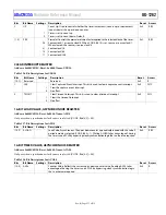
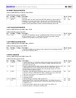
16-BIT TIMER VALUE, ASYNCHRONOUS REGISTER
Address: 0x400C0E18, Reset: 0x0000, Name: ACURCNT
Only use when a synchronous clock source is selected (CTL, Bits[6:5] = 00).
Table 368. Bit Descriptions for ACURCNT
Bits Bit
Name Settings Description
Reset Access
[15:0] VALUE
Counter Value. Reflects the current up or down counter value. Reading this register
takes advantage of having the timer run on PCLK by bypassing clock synchronization
logic that is otherwise required.
0x0 R
STATUS REGISTER
Address: 0x400C0E1C, Reset: 0x0000, Name: STAT
Table 369. Bit Descriptions for STAT
Bits Bit
Name Settings Description
Reset Access
[15:9] Reserved
Reserved.
0x0 R
8 CNTRST
Counter Reset Occurring. Indicates that the counter is currently being reset due to an
event detection. CTL, Bit 14 must be set.
0x0 R
7 PDOK
Clear Interrupt Register Synchronization. This bit is set automatically when the user
sets CLRINT, Bit 0 = 1. This bit is cleared automatically when the clear interrupt request
has crossed clock domains and taken effect in the timer clock domain.
0x0 R
1
The clear timeout interrupt bit is being updated in the timer clock domain.
0
The interrupt is cleared in the timer clock domain.
6 BUSY
Timer Busy. This bit informs the user that a write to CTL is still crossing into the timer clock
domain. Check this bit after writing CTL and suppress further writes until this bit is cleared.
0x0 R
0
Timer ready to receive commands to control register.
1
Timer not ready to receive commands to control register.
[5:1] Reserved
Reserved.
0x0 R
0 TIMEOUT
Timeout Event Occurred. This bit is set automatically when the value of the counter
reaches zero while counting down or reaches full scale when counting up. This bit is
cleared when CLRINT, Bit 0 is set by the user.
0x0 R
0
No timeout event has occurred.
1
A timeout event has occurred.
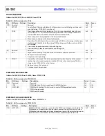
PWM CONTROL REGISTER
Address: 0x400C0E20, Reset: 0x0000, Name: PWMCTL
Table 370. Bit Descriptions for PWMCTL
Bits Bit
Name Settings Description
Reset Access
[15:2] Reserved
Reserved.
0x0 R
1
IDLESTATE
PWM Idle State. Used to set the PWM idle state.
0x0
R/W
0
PWM idles low.
1
PWM idles high.
0
MATCH
PWM Match Enabled. Used to control PWM operational mode.
0x0
R/W
0
PWM in toggle mode.
1
PWM in match mode.
PWM MATCH VALUE REGISTER
Address: 0x400C0E24, Reset: 0x0000, Name: PWMMATCH
Table 371. Bit Descriptions for PWMMATCH
Bits Bit
Name Settings Description
Reset Access
[15:0] VALUE
PWM Match Value. The value is used when the PWM is operating in match mode. The PWM
output is asserted when the up or down counter is equal to this match value. PWM output
is deasserted again when a timeout event occurs. If the match value is never reached, or
occurs simultaneous to a timeout event, the PWM output remains idle.
0x0 R/W


