


UG-1262
Rev. B | Page 90 of 312
To control the switches individually, use the LPDACSWx registers. LPDACSWx, Bit 5 must be set to 1 so that each switch can be
individually controlled via LPDACSWx, Bits[4:0].
Relationship Between 12-Bit and 6-Bit Outputs, Hardware Compensation Enabled
The 12-bit and 6-bit outputs are mostly independent. However, the selected 12-bit value does have a loading effect on the
6-bit output that must be compensated for in user code, particularly when the 12-bit output level is greater than the 6-bit output.
When the 12-bit output < 6-bit output,
12-Bit DAC Output Voltage
= 0.2 V + (
LPDACDATx, Bit
s[11:0]
×
0.54
mV)
(5)
6-Bit DAC Output Voltage
= 0.2
V
+ (
LPDACDATx, Bits[17:12]
×
34.38
mV)
(6)
When the 12-bit output is greater than or equal to 6-bit output,
12-Bit DAC Output Voltage
= 0.2 V + (
LPDACDATx, Bits[11:0]
× 0.54 mV) + 0.54 mV
(7)
6-Bit DAC Output Voltage
= 0.2 V + (
LPDACDATx, Bits[17:12]
×
34.38
mV)
(8)
where 0.54 mV is approximately 1 LSB of the 12-bit DAC and 34.38 mV is approximately 1 LSB of the 6-bit DAC.
In user code, it is recommended to add the following:
12BITCODE = LPDACDATx[11:0];
6BITCODE = LPDACDATx[17:12];
if (12BITCODE > (6BITCODE *64))
LPDACDATx[11:0] = (12BITCODE – 1);
If LPDACDATx, Bits[11:0] = 4095, the minimum voltage on the 12-bit output is 2.39946 V, because LPDACDATx, Bits[11:0] = 4095 has
the same effect as LPDACDATx, Bits[11:0] = 4094.
Low Power DAC Use Cases
Electrochemical Amperometric Measurement
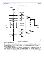
In an electrochemical measurement, the 12-bit output sets the voltage on the reference electrode pin via the potentiostat circuit shown in
Figure 20. The voltage on the CE0 and RE0 pins is V
BIAS
. The 6-bit output sets the bias voltage on the low power TIA positive pin, which
in turn sets the voltage on SE0. This voltage is V
ZERO
. The bias voltage on the sensor effectively becomes the difference between the 12-bit
output and the 6-bit output.
16
67
5
-12
3
PA
DUAL-OUTPUT
DAC
+
LPTIA
–
SE0
MU
X
SENSOR
RE0
R
TIA
V
BIAS
V
ZERO
CE0
Figure 20. Electrochemical Standard Configuration
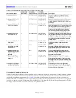
Recommended Switch Settings for Various Operating Modes
Table 106 details the recommended switch settings in the low power potentiostat loop for various measurement types. For all
measurement types, setting to 1 closes the switch and setting to 0 opens the switch. LPTIASWx, Bits[13:0] control SW13 to SW0 in
Figure 16 and Figure 17.


