


UG-1262
Rev. B | Page 274 of 312
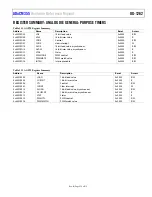
ANALOG DIE GENERAL-PURPOSE TIMERS
ANALOG DIE GENERAL-PURPOSE TIMERS FEATURES
analog die integrates two identical general-purpose, 16-bit count up or count down timers: AGPT0 and AGPT1. The timers
can be clocked from the 32 kHz internal low frequency oscillator on the analog die, the analog die PCLK, internal 16 MHz or 32 MHz high
frequency oscillator, or the external clock input. Clock sources can be scaled down using a prescaler to 1, 4, 16, or 256. Free running
mode and periodic modes are available. The timers have a PWM output feature. Configure the INTEN register to enable AFE general-
purpose timer interrupts.
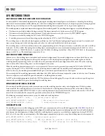
AFE PWM
The AFE die in the ADuCM355 has a dedicated PWM output feature. The high period for the PWM is the difference between the values
in the timer load register and either the PWMMAT0 register or PWMMATCH register. The low period for the PWM is the difference
between either the PWMMAT0 register or PWMMATCH register and the overflow value 0xFFFF. Increasing and reducing the load
value increases and reduces the frequency of the PWM output.
The following example sets up the PWM for a duty cycle of 2 ms (high) period and 1.56 ms (low) period:
void PWM1Init(void)
{
AfeDioCfgPin(pADI_AGPIO2, PIN1, 1);
/*1MHz GPT clock, count up, periodic */
AfeGptCfg(pADI_AGPT1, TCTL_CLK_PCLK, TCTL_PRE_DIV16, BITM_TMR_CTL_UP|BITM_TMR_CTL_MODE);
/*count 2000, 2ms period: 64000 – 62000, assuming 16MHz clock and prescaler of 16 */
AfeGptLd(pADI_AGPT1,62000);
/*Low period is 65535-64000*/
AfePwmCfg(pADI_AGPT1, PWM_IDLEHI, PWM_MATCH_MODE);
AfePwmMatch(pADI_AGPT1, 64000);
/*start timer, output PWM*/
pADI_AGPT1->CON1 |= BITM_TMR_CTL_EN;
}


