


UG-1262
Rev. B | Page 261 of 312
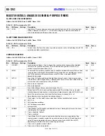
INTERRUPT IDENTIFICATION REGISTER
Address: 0x40005008, Reset: 0x0001, Name: COMIIR
Table 324. Bit Descriptions for COMIIR
Bits Bit
Name Settings
Description
Reset Access
[15:8] Reserved
Reserved.
0x0 R
[7:6] FEND
FIFO
Enabled.
0x0 R
00
FIFO not enabled, 16450 UART mode.
11
FIFO enabled, 16550 UART mode.
[5:4] Reserved
Reserved.
0x0 R
[3:1] STA
Interrupt Status. When NIRQ is active low, this bit indicates an interrupt and the
following decoding for this bit is used.
0x0 RC
000
Modem status interrupt. Read COMMSR to clear.
001
Transmit buffer empty interrupt. Write to COMTX or read COMIIR to clear.
010
Receive buffer full interrupt. Read COMRX to clear.
110
Receive FIFO timed out. Read COMRX to clear.
011
Receive line status interrupt. Read COMLSR to clear.
0 NIRQ
Interrupt
flag.
0x1
RC
LINE CONTROL REGISTER
Address: 0x4000500C, Reset: 0x0000, Name: COMLCR
Table 325. Bit Descriptions for COMLCR
Bits Bit
Name
Settings
Description
Reset Access
[15:7] Reserved
Reserved.
0x0 R
6 BRK
Set
Break.
0x0 R/W
1
Force UART_SOUT pin to 0.
0
Normal UART_SOUT pin operation.
5 SP
Stick Parity. Used to force parity to defined values. When set, the parity is based on the
following bit settings: When EPS = 1 and PEN = 1, the parity is forced to 0. When EPS = 0
and PEN = 1, the parity is forced to 1. When EPS = X and PEN = 0, no parity is transmitted.
0x0 R/W
0
Parity is not forced based on EPS and PEN.
1
Parity forced based on EPS and PEN.
4
EPS
Parity Select. This bit only has meaning if parity is enabled (PEN set).
0x0
R/W
0
Odd parity is transmitted and checked.
1
Even parity is transmitted and checked.
3 PEN
Parity Enable. This bit is used to enable parity to be transmitted and checked. The value
transmitted and the value checked are based on the settings of EPS and SP.
0x0 R/W
0
Parity is not transmitted or checked.
1
Parity is transmitted and checked.
2 STOP
Stop Bit. Used to control the number of stop bits transmitted. In all cases, only the first
stop bit is evaluated when data is received.
0x0 R/W
0
Send one stop bit regardless of the word length in the WLS bit.
1
Send a number of stop bits based on the word length. Transmit 1.5 stop bits if the word
length is 5 bits (WLS = 00), or 2 stop bits if the word length is 6 (WLS = 01), 7 (WLS = 10),
or 8 bits (WLS = 11).
[1:0]
WLS
Word Length Select. Selects the number of bits per transmission.
0x0
R/W
00
5
bits.
01
6
bits.
10
7
bits.
11
8
bits.


