UG-1262
Rev. B | Page 294 of 312
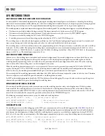
Bits Bit
Name
Settings Description
Reset Access
3 ISOINT
WUT Power Domain Isolation Interrupt Source. ISOINT is a sticky interrupt source that
indicates whether the WUT has had to activate its power domain isolation barrier due to
a power loss in the core. When the core regains power, the CPU can read ISOINT to
inform itself of such a power event. Cleared by writing a value of one to this bit.
0x1 R/W1C
0
The always on WUT power domain has not activated its isolation from the core
since the ISOINT interrupt source was last cleared by the CPU.
1
The always on WUT power domain has activated and subsequently deactivated its
isolation from the core due to a power event. This event occurred since ISOINT was
last cleared by the CPU. Clear bit by writing a 1.
2 MOD60ALMINT
Modulo 60 WUT Alarm Interrupt Source. MOD60ALMINT is a sticky flag that is the
source of an optionally enabled interrupt to the CPU. This interrupt is activated
once every 60 increments of CNT1 and CNT0, at a displacement of MOD60ALM
increments past a modulo 60 boundary. Cleared by writing 1 to this bit.
0x0 R/W1C
0
A MOD60ALMINT interrupt event has not occurred since this bit was last cleared by
the CPU.
1
A MOD60ALMINT interrupt event has occurred since this bit was last cleared by the CPU.
1 ALMINT
Alarm Interrupt Source. ALMINT is a sticky flag that is the source of an optionally
enabled interrupt to the CPU. ALMINT indicates that an alarm event has occurred
due to a match between the WUT count and alarm register values. A match is
defined as the value in CNT1, CNT0, and CNT2, equating to the alarm time given by
ALM1, ALM0, and ALM2. The detection of such an event is enabled by ALMEN in
CR0. ALMINT is cleared by writing 1 to this bit.
0x0 R/W1C
0
An ALMINT interrupt event has not occurred since this bit was last cleared by the CPU.
1
An ALMINT interrupt event has occurred since this bit was last cleared by the CPU.
0 Reserved
Reserved.
0x0 R
STATUS 1 REGISTER
Address: 0x40001408, Reset: 0x0078, Name: SR1
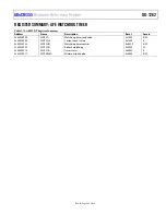
Table 382. Bit Descriptions for SR1
Bits
Bit
Name
Settings Description
Reset Access
[15:13] Reserved
Reserved.
0x0
R
12 WPNDALM1
Pending Status of Posted Writes to the ALM1 Register. WPNDALM1 indicates if a
posted register write to ALM1 is currently pending.
0x0 R
0
The WUT can accept a new posted write to the ALM1 MMR.
1
A previously posted write to ALM1 is still awaiting execution. No new posting to this
MMR can be accepted.
11 WPNDALM0
Pending Status of Posted Writes to the ALM0 Register. WPNDALM0 indicates if a
posted register write to ALM0 is currently pending.
0x0 R
0
The WUT can accept a new posted write to the ALM0 MMR.
1
A previously posted write to ALM0 is still awaiting execution. No new posting to this
MMR can be accepted.
10 WPNDCNT1
Pending Status of Posted Writes to the CNT1 Register. WPNDCNT1 indicates if a
posted register write to CNT1 is currently pending.
0x0 R
0
The WUT can accept a new posted write to the CNT1 MMR.
1
A previously posted write to CNT1 is still awaiting execution. No new posting to this
MMR can be accepted.
9 WPNDCNT0
Pending Status of Posted Writes to the CNT0 Register. WPNDCNT0 indicates if a
posted register write to CNT0 is currently pending.
0x0 R
0
The WUT can accept a new posted write to the CNT0 MMR.
1
A previously posted write to CNT0 is still awaiting execution. No new posting to this
MMR can be accepted.
8 WPNDSR0
Pending Status of Posted Clearances of Interrupt Sources in the SR0 Register.
WPNDSR0 indicates if posted clearances of interrupt sources in SR0 are currently
pending. Clearances can always be accepted and accumulated into the same
pending transaction for SR0. As such, accumulation is nondestructive of previously
posted clearances. This is in contrast to other MMRs, where posted write data
(rather than posted clearances) cannot be aggregated into one transaction.
0x0 R


