


UG-1262
Rev. B | Page 108 of 312
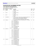
HIGH SPEED DAC CIRCUITS
The 12-bit high speed DAC generates an ac excitation signal when measuring the impedance of an external sensor. The DAC output
signal can be controlled directly by writing to a data register or by the automated waveform generator block. The high speed DAC signal
is fed to an excitation amplifier designed specifically to couple the ac signal on top of the normal dc bias voltage of the sensor. Alternatively, the
high speed DAC can be used as a normal voltage source. See the Calibrating the High Speed DAC section for more details.
DAC CODE DIRECT
WAVEFORM
GENERATOR
RECONSTRUCTION
FILTER
PROGRAMMABLE
GAIN
AMPLIFIER
HIGH
SPEED
DAC
V
BIAS
FROM LPDAC
V
ZERO
FROM LPDAC
EXCITATION
AMPLIFIER
OUTPUT
D
+
–
16
67
5-
0
22
Figure 23. Overview of High Speed DAC Blocks
HIGH SPEED DAC OUTPUT SIGNAL GENERATION
There are two ways of setting the high speed DAC output voltage, which are as follows:
Direct write to the DAC code register. Write to the HSDACDAT register, a 12-bit register where the MSB is a sign bit. A value of
0x800 results in a 0 V output. 0xFFF is positive full scale. 0x000 is negative full scale.
Use the automatic waveform generator. The waveform generator can be programmed to generate fixed frequency and fixed
amplitude signals. If the user selects the sine wave, options exist to adjust the offset and phase of the output signal.
To use the waveform generator to generate a sine wave, follow these steps:
1.
Set AFECON, Bit 14 = 1 to turn on the waveform generator.
2.
Set WGCON, Bits[2:1] = 10 to select sine waveforms.
3.
Set WGAMPLITUDE, Bits[10:0] to set up the sine wave amplitude. The sine wave automatically swings above or below the
common-mode voltage. As such, there are only 11 bits required for the amplitude control.
4.
Set WGFCW, Bits[23:0] to set the sine wave output frequency. For output frequencies higher than 80 kHz, the high speed DAC
must be configured for high power mode. See the Power Mode Configuration Register section for more details. For this
configuration, use the equation
30
2
OUT
ACLK
WGFCW Bits[23 : 0]
f
f
(9)
where:
f
OUT
is the output frequency.
f
ACLK
is the analog clock frequency, 16 MHz.
HIGH SPEED DAC CORE POWER MODES
The reference source of the high speed DAC is an internal 1.8 V precision reference voltage.
There are three basic modes of operation of the high speed DAC that trade power consumption and output speed.
Low Power Mode
When configuring the high speed DAC for low power mode, take note of the following requirements and features:
Clear PMBW, Bit 0 = 0 to minimize current consumption. This setting is recommended when the high speed DAC output
frequency must be ≤80 kHz.
In low power mode, the system clock to the DAC and the ADC is 16 MHz.
Ensure that CLKSEL, Bits[1:0] selects a 16 MHz clock source. For example, an internal high speed oscillator is selected if
CLKSEL, Bits[1:0] = 00. Ensure that the system clock divide ratio is 1 (CLKCON0, Bits[5:0] = 0 or 1).
If the internal high speed oscillator is selected as the system clock source, ensure that the 16 MHz option is selected. Set
HPOSCCON, Bit 2 = 1.
High Power Mode
When configuring the high speed DAC for high power mode, take note of the following requirements and features:
Increases the bandwidth supported by the high speed DAC amplifiers.
Set PMBW, Bit 0 = 1. Power consumption is increased, but the output signal bandwidth increases to a maximum of 200 kHz.
In this mode, the system clock to the DAC and the ADC must be 32 MHz.