


UG-1262
Rev. B | Page 267 of 312
DIGITAL DIE GENERAL-PURPOSE TIMERS
DIGITAL DIE GENERAL-PURPOSE TIMERS FEATURES
The
digital die integrates three identical general-purpose, 16-bit count up or count down timers: Timer 0, Timer 1, and
Timer 2. These timers can be clocked from the 32 kHz internal low frequency oscillator, the PCLK, or the internal 26 MHz high
frequency oscillator. Clock sources can be scaled down using a prescaler to 1, 4, 16, or 256. Free running mode and periodic mode are
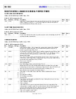
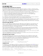
available. The timers have a capture events feature, with the capability to capture 32 different events on each timer. See Figure 64 for an
overview of the general-purpose timers.
1667
5-
152
TIMER
RESET
CAPTURE
16 IRQ EVENTS
CAPTURE
TIMER VALUE
CLOCK
SOURCES
8-BIT PRESCALE
(1, 4, 16, 64, 256)
16-BIT UP/DOWN COUNTER
IRQ
GEN
IRQ
16-BIT LOAD
Figure 64. General-Purpose Timers Block Diagram
GENERAL-PURPOSE TIMERS OVERVIEW
The timers can either be in free running mode or periodic mode. In free running mode, the counter decrements from full scale to zero
scale or increments from zero scale to full scale and then restarts. In periodic mode, the counter decrements or increments from the value
in the load register (GPTx_LOAD, where x is 0 for Timer 0, 1 for Timer 1, and 2 for Timer 2) until zero scale or full scale is reached. The
counter then restarts at the value stored in the load register.
The value of a counter can be read at any time by accessing its value register, GPTx_ACURCNT or GPTx_CURCNT. GPTx_ACURCNT
assumes the timer and the CPU are synchronized (using the same clock source). Do not use GPTx_ACURCNT if the timer is using a
different clock source, such as the low frequency oscillator. In this case, use GPTx_CURCNT. GPTx_CURCNT returns a synchronized
timer value but has a slightly delayed result owing to the synchronization period required.
The CON0 register selects the timer mode, configures the clock source, selects count up or count down, starts the counter, and controls
the event capture function.
An interrupt signal is generated each time the value of the counter reaches 0 when counting down or each time the counter value reaches the
maximum value when counting up. Clear an IRQ by writing 1 to the time clear interrupt register of that particular timer (GPTx_CLRINT).
In addition, Timer 0, Timer 1, and Timer 2 have a capture register that is triggered by a selected IRQ source initial assertion. When
triggered, the current timer value is copied to the GPTx_CAPTURE register, and the timer continues to run. This feature determines the
assertion of an event with increased accuracy.
GENERAL-PURPOSE TIMER OPERATIONS
Free Running Mode
In free running mode, the timer is started by setting the enable bit (GPTx_CTL, Bit 4) to 1 and the mode bit (GPTx_CTL, Bit 3) to 0. The
timer increments from zero scale or full scale to full scale or zero scale if counting up or down. Full scale is 216, which is 1 or 0xFFFF.
Upon reaching full scale or zero scale, a timeout interrupt occurs and GPTx_STAT, Bit 0 is set. To clear the timer interrupt, user code
must write 1 to GPTx_CLRINT, Bit 0. If GPTx_CTL, Bit 7 is set, the timer keeps counting and reloads when GPTx_CLRINT, Bit 0 is set to 1.
Periodic Mode
In periodic mode, the initial GPTx_LOAD value must be loaded before starting the timer by setting the enable bit (GPTx_CTL, Bit 4) to
1. The timer value either increments from the value in GPTx_LOAD to full scale or decrements from the value in GPTx_LOAD to zero
scale, depending on the GPTx_CTL, Bit 2 settings (count up or down). Upon reaching full scale or zero scale, the timer generates an
interrupt. GPTx_LOAD is reloaded into GPTx_CURCNT, and the timer continues counting up or down. The timer must be disabled
prior to changing the GPTx_CTL or GPTx_LOAD register. If the GPTx_LOAD register is changed while the timer is being loaded,


