


4.4 External Dimensions
4.4.6 SGLFW2-1D
4-32
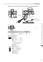
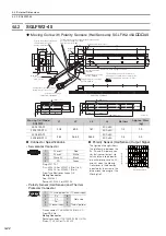
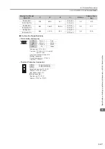
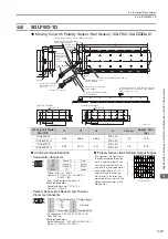
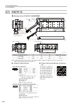
Moving Coil without Polarity Sensor (Hall Sensor): SGLFW2-1DA
AT1
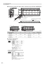
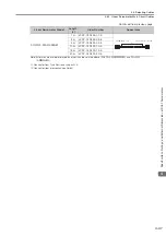
Moving Coil Model
SGLFW2-
L1
L2
L3
L4
Flatness
Approx. Mass
[kg]
1DA380AT1
384
268.5
365.5
300
±
30
0.3
14.6
1DA380AT1H
500
±
50
1DA560AT1
563
447.5
544
300
±
30
0.3
21.5
1DA560AT1H
500
±
50
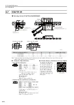
Connector Specifications
•
Servomotor Connector
Tab housing: 1-917808-2
Contacts: 917803-2 (A1, A2, and B1)
84695-1 (B2)
From Tyco Electronics Japan G.K.
Mating Connector
Receptacle housing: 1-917807-2
Contacts: 179956-2
•
Polarity Sensor (Hall Sensor) and Thermal
Protector Connector
Pin connector: 17JE-23090-02 (D8C) -CG
From DDK Ltd.
Mating Connector
Socket connector: 17JE-13090-02 (D8C) A-CG
Studs: 17L-002C or 17L-002C1
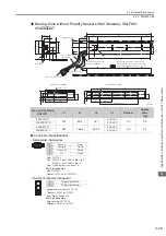
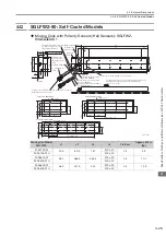
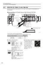
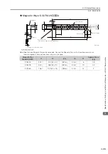
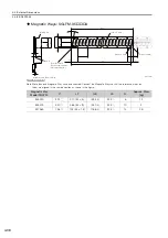
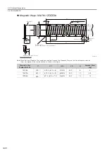
Magnetic Way
Servomotor Main
Circuit Cable
UL2586, AWG12
Servomotor connector
60 min.
Thermal protector cable
UL1333, AWG20
Thermal protector connector
(10.5 dia.)
The Moving Coil moves in the direction indicated
by the arrow when current flows in the following
phase sequence: U, V, W.
Unit: mm
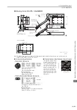
Refer to the following table.
Refer to the following figures
and
.
(87.5)
(87.5)
175
(11.2)
67.5
20
±
0.1
136
160
15
50±0.1
2
(36)
38±0.1
(6)
22.5
(5)
45
45
(9)
L4
Gap 0.8
48.5
(55)
L1
L2
12
L3
100
±20
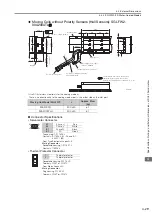
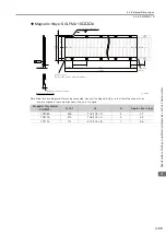
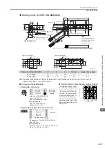
SGLFW2-1DA560AT
60.5
89.5
447.5 (89.5 × 5)
82.5
18 × M8 × 16
136
15
45
45
22.5
SGLFW2-1DA380AT
60.5
89.5
268.5 (89.5 × 3)
82.5
136
15
45
45
22.5
12 × M8 × 16
A1
B1
B2
A2
A1
Phase U
Red
A2
Phase V
White
B1
Phase W
Black
B2
FG
Green
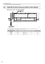
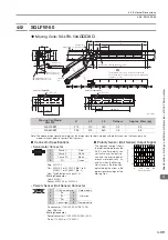
9
6
5
1
1
+5 V (thermal protector), +5 V (power supply)
2
Su
6
Not used
3
Sv
7
4
Sw
8
5
0 V (power supply)
9
Thermal protector