


7.2 Installation Procedure
7.2.2 SGLF Servomotors (Models with F-type Iron Cores)
7
S
ervomotor In
s
tallation
7-7
1.
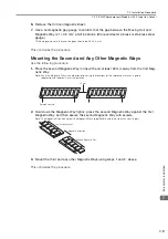
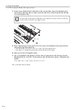
Remove the dummy plates to reduce magnetic force and the cardboard from the surface
of the Magnetic Way.
2.
Face the reference marks on the Magnetic Way (depressions of approx. 4 mm in diame-
ter) toward the equipment and set down the Magnetic Way.
Note: Be careful not to pinch your hands between the equipment and the Magnetic Way.
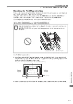
3.
Press the Magnetic Way tightly against the equipment and secure it with screws.
Note:Use socket head screws with a strength class of 10.9.
This concludes the procedure.
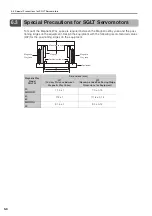
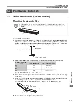
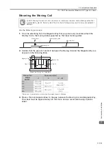
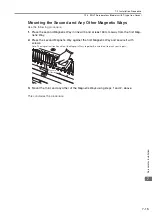
Mounting the Moving Coil
Use the following procedure.
1.
On a line extending from the Magnetic Way that you previously mounted, attach the
Moving Coil to the moving table supported by the linear motion guides.
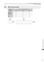
2.
Confirm that the gap, G, between the Moving Coil and the Magnetic Way are as given in
the following table.
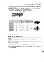
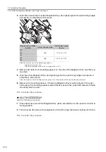
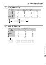
Magnetic Way
Model
Screw Nominal
Size
Tightening
Torque
(N
cm)
Screw Head
Height, K
(mm)
Reference
SGLFM-20
M4
360 to 500
4.2 max.
Figure 1
SGLFM-35
SGLFM-50
M5
720 to 1,010
5.2 max.
SGLFM-1Z
M6
1,220 to 1,710
6.7 max.
Figure 2
SGLFM2-30
M4
360 to 500
4.2 max.
SGLFM2-45
M5
720 to 1,010
5.2 max.
SGLFM2-90
M6
1,220 to 1,710
6.7 max.
SGLFM2-1D
M8
2,970 to 4,150
8.2 max.
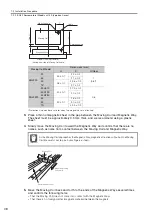
An SGLF Moving Coil consists of an iron core and a winding section that is protected by plastic.
Do not subject them to shock. Doing so may result in injury or equipment damage.
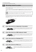
Magnetic Way connecting section
Mounting surface
Reference mark
Reference mark
Magnet
Magnetic
Way yoke
K
Figure 1
Figure 2
Magnet
Magnetic
Way yoke
K
Note