


4.1 Model Designations
4.1.3 Precautions on Moving Coils with Polarity Sensors (Hall Sensors)
4
S
pecification
s
, Rating
s
, and Exter
nal Dimen
s
ion
s
of
SG
LF
S
ervomotor
s
4-5
4.1.3
Precautions on Moving Coils with Polarity Sensors
(Hall Sensors)
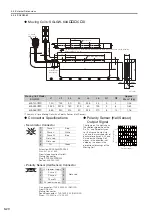
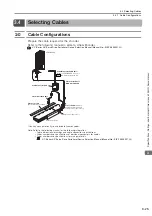
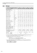
When you use a Moving Coil with a Polarity Sensor (Hall Sensor), the Magnetic Way must cover
the bottom of the polarity sensor (hall sensor). Refer to the example that shows the correct instal-
lation.
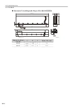
When determining the length of the Moving Coil’s stroke or the length of the Magnetic Way, con-
sider the total length (L) of the Moving Coil and the polarity sensor (hall sensor). Refer to the fol-
lowing table.
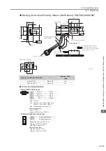
Correct Installation
Incorrect Installation
Total Length of Moving Coil with
Polarity Sensor (Hall Sensor)
Note
Polarity sensor
(hall sensor)
Moving Coil
movement direction
Magnetic Way
Moving Coil
Edge of Magnetic Way
Polarity sensor
(hall sensor)
Edge of Magnetic Way
L
L1
A
Moving Coil
Magnetic Way
Polarity sensor (hall sensor)
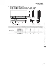
Moving Coil
Model
SGLFW2-
Length of
Moving
Coil,
L1 [mm]
Length of
Polarity
Sensor
(Hall Sensor),
A [mm]
Total
Length,
L [mm]
30A070AS
70
27
97
30A120AS
125
152
30A230AS
230
257
45A200AS
205
32
237
45A380AS
384
416
90A200AS
205
32
237
90A380AS
384
416
90A560AS
563
595
1DA380AS
384
32
416
1DA560AS
563
595
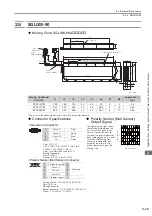
Moving Coil
Model
SGLFW-
Length of
Moving
Coil,
L1 [mm]
Length of
Polarity
Sensor
(Hall Sensor),
A [mm]
Total
Length,
L [mm]
20A090AP
91
22
113
20A120AP
127
149
35A120AP
127
22
149
35A230AP
235
257
50A200BP
215
22
237
50A380BP
395
417
1ZA200BP
215
22
237
1ZA380BP
395
417