


3.3 External Dimensions
3.3.2 SGLGW-40
3
S
pecification
s
, Rating
s
, and Exter
nal Dimen
s
ion
s
of
SG
L
G
S
ervomotor
s
3-15
3.3.2
SGLGW-40
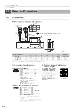
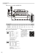
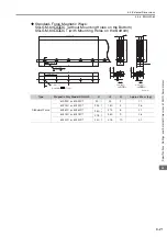
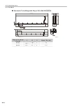
Moving Coils: SGLGW-40A
C
*
The mass is for a Moving Coil with a Polarity Sensor (Hall Sensor).
Moving Coil
Model
SGLGW-
L1
L2
L3
L4
L5
L6
N1
N2
Approx.
Mass
*
[kg]
40A140C
140
125
90
30
52.5
45
3
4
0.40
40A253C
252.5
237.5
180
37.5
60
135
5
8
0.66
40A365C
365
350
315
30
52.5
270
8
14
0.93
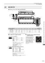
Connector Specifications
Polarity Sensor (Hall Sensor)
Output Signal
•
Servomotor Connector
The figure on the right shows
the relationship between the
Su, Sv, and Sw polarity sen-
sor (hall sensor) output sig-
nals and the inverse power of
each motor phase Vu, Vv,
and Vw when the Moving
Coil moves in the direction
indicated by the arrow in the
dimensional drawings of the
Moving Coil.
Plug: 350779-1
Pins: 350561-3 or 350690-3 (No.1 to 3)
350654-1 or 350669-1 (No. 4)
From Tyco Electronics Japan G.K.
Mating Connector
Cap: 350780-1
Socket: 350570-3 or 350689-3
•
Polarity Sensor (Hall Sensor) Connector
Pin connector: 17JE-23090-02 (D8C)-CG
From DDK Ltd.
Mating Connector
Socket connector: 17JE-13090-02 (D8C)A-CG
Studs: 17L-002C or 17L-002C1
2 × #4-40 UNC screws
(5.3 dia.)
(7 dia.)
Polarity sensor
(hall sensor)
The Moving Coil moves in the direction indicated by the arrow when current flows in the following phase
sequence: U, V, W.
N1 × M4 × 6 (both sides)
Unit: mm
N2
×
M4
×
6
15
63
30
4
(7.5)
17
L5
L6
45
L1
L3
16
L4
45
L2
500
±
50
500
±
50
15
1
25.4
Gap 0.8
Gap 0.8
25.4
78
62
5.8
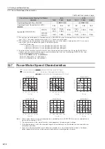
Vu
Vv
Vw
Su
Sv
Sw
0
180
360
540
Electrical angle (°)
Inverse power (V)
1
2
3
4
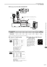
1
Phase U
Red
2
Phase V
White
3
Phase W
Blue
4
FG
Green
9
6
5
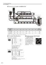
1
1
+5 V (power supply)
6
Not used
2
Phase U
7
3
Phase V
8
4
Phase W
9
5
0 V (power supply)
−
−