


4.4 External Dimensions
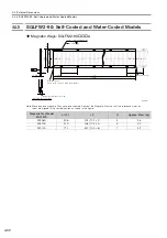
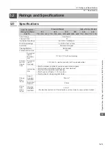
4.4.8 SGLFW-35
4
S
pecification
s
, Rating
s
, and Exter
nal Dimen
s
ion
s
of
SG
LF
S
ervomotor
s
4-37
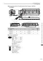
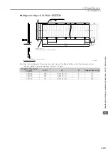
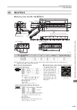
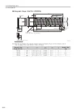
Moving Coils: SGLFW-35A
A
D
Note: The above dimensional drawing gives the dimensions for both models with polarity sensors (hall sensors) and
models without polarity sensors (hall sensors).
Moving Coil Model SGLFW-
L1
L2
L3
Flatness
Approx. Mass [kg]
35A120A
D
127
72
108
0.1
1.3
35A230A
D
235
180
216
0.2
2.3
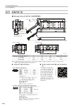
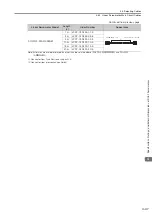
Connector Specifications
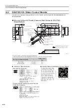
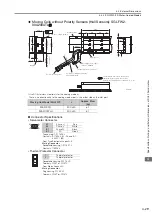
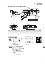
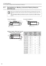
Polarity Sensor (Hall Sensor) Output Signal
•
Servomotor Connector
The figure on the right shows
the relationship between the
Su, Sv, and Sw polarity sen-
sor (hall sensor) output sig-
nals and the inverse power
of each motor phase Vu, Vv,
and Vw when the Moving
Coil moves in the direction
indicated by the arrow in the
dimensional drawings of the
Moving Coil.
Extension: ARRA06AMRPN182
Pins: 021.279.1020
From Interconnectron GmbH
Mating Connector
Plug: APRA06BFRDN170
Socket: 020.105.1020
•
Polarity Sensor (Hall Sensor) Connector
Pin connector: 17JE-23090-02 (D8C)-CG
From DDK Ltd.
Mating Connector
Socket connector: 17JE-13090-02 (D8C)A-CG
Studs: 17L-002C or 17L-002C1
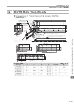
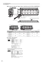
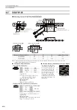
SGLFW-35A120A
D
SGLFW-35A230A
D
30
36
6
M4
8
(35)
18
(30)
(8.5)
(12.5)
72
12
M4
8
(35)
18
(8.5)
(12.5)
30
36
180 (36
5)
(30)
12
500
50
500
50
7
L1
30
(10.5)
(12.5)
(7.5)
(35)
L3
L2
30
25
36
(8.5)
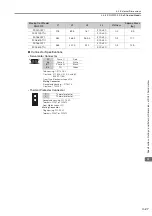
9.7 dia.
18
50 min.
Polarity sensor
(Hall sensor)
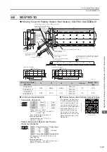
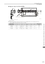
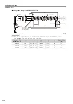
Magnetic Way
2 × #4-40 UNC
screws
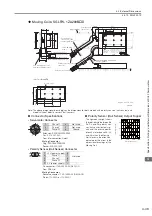
Refer to the following
figures
and
.
(4.2 dia.)
(6.1 dia.)
30 min.
The Moving Coil moves in
the direction indicated by the
arrow when current flows in
the following phase
sequence: U, V, W.
Unit: mm
5.5
2
45
0.1
34
(32)
0.5
7.7
(6)
55
43
(30)
(2
5
)
12.5
(30)
(30)
(60)
(35)
37
(10.2 with magnet cover)
(10 without magnet cover)
(4.2 with magnet cover)
(4 without magnet cover)
(Gap: 0.8 with magnet cover)
(Gap: 1 without magnet cover)
Refer to the following table.
Vu
Vv
Vw
Su
Sv
Sw
0
180
360
540
Electrical angle (°)
Inverse power (V)
6
5
4
1
2
1
Phase U
5
Not used
2
Phase V
6
Not used
4
Phase W
Ground
9
6
5
1
1
+5 V (power supply)
6
Not used
2
Phase U
7
3
Phase V
8
4
Phase W
9
5
0 V (power supply)
−
−