


7.2 Installation Procedure
7.2.2 SGLF Servomotors (Models with F-type Iron Cores)
7
S
ervomotor In
s
tallation
7-5
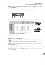
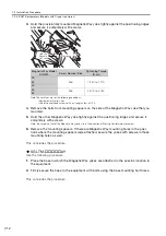
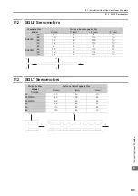
3.
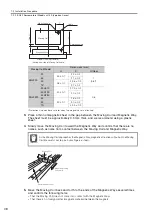
Confirm that the gap, G, between the winding section of the Moving Coil and the mag-
nets of the Magnetic Way are as given in the following table.
4.
Move the Moving Coil back and forth to the ends of the Magnetic Ways several times
and confirm the following items.
•
That the Moving Coil does not come into contact with the Magnetic Ways
•
That there is no foreign matter (magnetic material) between the magnets
This concludes the procedure.
7.2.2
SGLF Servomotors (Models with F-type Iron Cores)
Outline
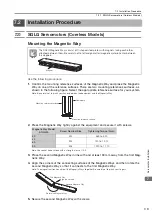
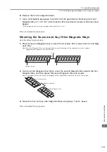
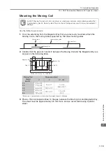
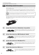
1.
Mount one Magnetic Way.
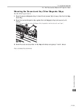
2.
Separate the moving table that is supported by the linear motion guides from the Mag-
netic Way and attach the Moving Coil to it.
Moving Coil
Magnetic Way
G
G
H
P
Moving Coil
Model
SGLGW-
Dimensions (mm)
H
P
G
30A050
1
±
0.3
1
±
0.1
0.85
±
0.3
30A080
1
±
0.3
1
±
0.1
0.95
±
0.3
40
1
±
0.3
0
±
0.1
0.8
±
0.3
60
1
±
0.3
0
±
0.1
0.8
±
0.3
90
2
±
0.3
0.9
±
0.1
1
±
0.3
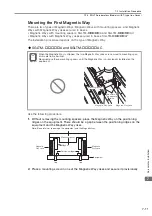
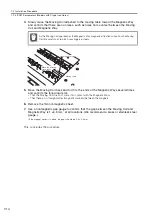
To install the Moving Coil, you need a Magnetic Way that is longer than the Moving Coil. If
one Magnetic Way is shorter than the Moving Coil, install two Magnetic Ways first and then
install the Moving Coil.
Important
Linear motion guide
Magnetic Way
Moving table
Moving Coil