


7.2 Installation Procedure
7.2.3 SGLT Servomotors (Models with T-type Iron Cores)
7
S
ervomotor In
s
tallation
7-13
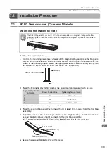
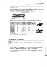
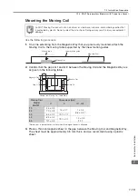
Mounting the Moving Coil
Use the following procedure.
1.
On a line extending from the Magnetic Way that you previously mounted, attach the
Moving Coil to the moving table supported by the linear motion guides.
2.
Confirm that the gaps, G1 and G2, between the Moving Coil and the Magnetic Way are
as given in the following table.
*
Dimensions in parentheses are for when the magnet cover is attached.
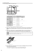
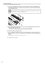
3.
Place a thin nonmagnetic sheet in the gap between the Moving Coil and Magnetic Way.
The sheet must be approximately 0.5 mm thick, and we recommend using a plastic
sheet.
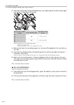
An SGLT Moving Coil consists of an aluminum or steel base, iron core, and a winding section that
is protected by plastic. Do not subject them to shock. Doing so may result in injury or equipment
damage.
Moving Coil
Model
SGLTW-
Dimensions (mm)
H
A
G1 , G2
20
55
±
0.3
15
±
0.1
1
±
0.3
(0.8
±
0.3)
*
35
70
±
0.3
50
85
±
0.3
19.1
±
0.1
40
83
±
0.3
19.1
±
0.1
1.4
±
0.3
(1.2)
*
80
120
±
0.3
Note
Linear motion guide
Magnetic Way
Moving table
Moving Coil
A
Magnetic Way
Magnetic Way
Gap, G1
Gap, G2
Moving Coil
Viewed from Moving Coil Cable Side
H