
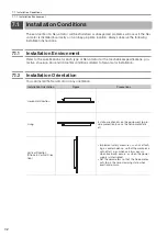


7.2 Installation Procedure
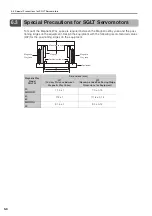
7.2.3 SGLT Servomotors (Models with T-type Iron Cores)
7-12
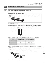
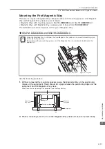
3.
Hold the provisionally mounted Magnetic Way yoke tightly against the positioning ridges
and secure it completely with screws.
Note:These values are for the following conditions.
•
Equipment materials: Iron
•
Use of socket head screws with a strength class of 10.9
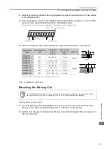
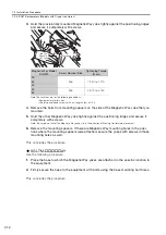
4.
Remove the bolts from mounting spacers on the side of the Magnetic Way yoke that you
mounted.
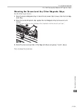
5.
Hold the other Magnetic Way yoke tightly against the positioning ridges and secure it
completely with screws.
Note: Be careful not to let the Magnetic Way yoke slip in the direction of Moving Coil forward movement.
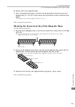
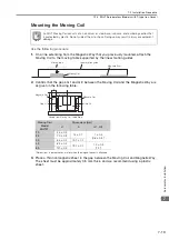
6.
Remove the mounting spacers. If there are Magnetic Way mounting holes in the posi-
tions where the mounting spacers were attached, secure the yokes with screws in those
mounting holes as well.
This concludes the procedure.
SGLTM-
AY
Use the following procedure.
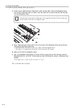
1.
Place the base to which the Magnetic Way yokes are attached in the specific location in
the equipment.
2.
Firmly secure the base to the equipment with bolts using the base mounting bolt holes.
This concludes the procedure.
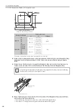
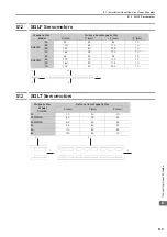
Magnetic Way Model
SGLTM-
Screw Nominal Size
Tightening Torque
(N
cm)
20
M6
1,220 to 1,710
35
50
40
M8
2,970 to 4,150
80
Hold the
Magnetic
Way yoke.
Positioning ridge