


9.1 Selecting Cables
9.1.4 Serial Converter Units
9-6
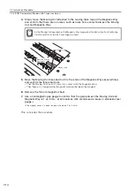
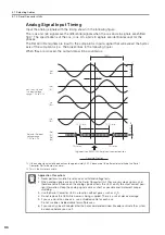
Analog Signal Input Timing
Input the analog signals with the timing shown in the following figure.
The /cos and /sin signals are the differential signals when the cos and sin signals are shifted
180
°
. The specifications of the cos, /cos, sin, and /sin signals are identical except for the
phases.
The Ref and /Ref signals are input to the comparator. Input a signal that will exceed the hyster-
esis of the comparator (i.e., the broken lines in the following figure).
When they are crossed, the output data will be counted up.
*1.
If the analog signal amplitude declines to approximately 0.35 V because of the differential amplitude, the Serial
Converter Unit will output an alarm.
*2.
This is the hysteresis width.
Application Precautions
1. Never perform insulation resistance or withstand voltage tests.
2. When analog signals are input to the Serial Converter Unit, they are very weak signals, and
therefore noise influence on the analog signals affects the Unit’s ability to output correct posi-
tion information. Keep the analog signal cable as short as possible and implement proper
shielding.
3. Use the Serial Converter Unit in a location without gases such as H
2
S.
4. Do not replace the Unit while power is being supplied. There is a risk of device damage.
5. If you use more than one axis, use a shielded cable for each axis.
Do not use one shielded cable for multiple axes.
6. If you use any Linear Encoder other than a recommended Linear Encoder, evaluate the system
in advance before you use it.
100%
12.5%
0.05 V
cos
(A+)
/cos
(A-)
sin
(B+)
/sin
(B-)
/Ref
(R-)
Ref
(R+)
*2
*1
Count-Up Direction
1.5 V to 3.5 V
Ref and /Ref input
voltage range:
cos, /cos, sin, and
/sin input voltage
range: 1.5 V to 3.5 V
12.5% min.
12.5% min.
Origin position, SERVOPACK origin pulse output position
75% max.
75% max.
0.2 V to 0.6 V
Important