


5.3 External Dimensions
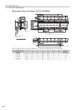
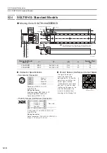
5.3.1 SGLTW-20: Standard Models
5
S
pecification
s
, Rating
s
, and Exter
nal Dimen
s
ion
s
of
SG
LT
S
ervomotor
s
5-11
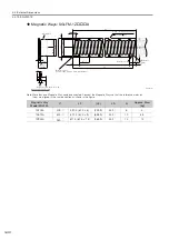
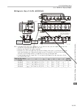
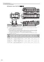
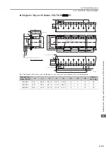
Magnetic Ways: SGLTM-20
A
Note: 1. Two Magnetic Way tracks are used together as a set. For safety, when they are shipped, the two tracks are
secured to a mounting spacer made from aluminum.
2. More than one Magnetic Way can be connected.
3. Dimensions with asterisks are the distances between the Magnetic Way tracks. Install the tracks according
to the specified dimensions. Observe the dimensions given in
Mounting
S
ection Details
after installation.
Dimensions when the Magnetic Way is shipped from the factory are indicated by
.
4. Use socket head screws of strength class 10.9 or higher for the Magnetic Way mounting screws. (Do not
use stainless steel screws.)
Magnetic Way
Model SGLTM-
L1
L2
LA
LB
LC
LD
N
Approx.
Mass [kg]
20324A
324
270 (54
×
5)
31.7
13.7
40.3
62
6
3.4
20540A
540
486 (54
×
9)
31.7
13.7
40.3
62
10
5.7
20756A
756
702 (54
×
13) 31.7
13.7
40.3
62
14
7.9
2
×
N
×
M6
×
8
C1
C1
(54)
L2
54
9.9
°
L2
54
(29.3)
(54)
R6
(54)
8
LC
L2
54
(29.3)
L1
L1
LA
LB
(9.4)
9.9
°
*
2.4
±
0.3
*
2.4
±
0.3
32
(8)
(55)
40
27
87
27
(1)
(100)
19
Gap1
±
0.3
15
15
*
70
±
0.3
*
70
±
0.3
LD
3
Moving Coil
2
N
7 dia. (Refer to
Side-to-Side Cro
ss
Section
for the depth.)
Spacers: Do not remove them
until the Moving Coil is mounted
on the machine.
Unit: mm
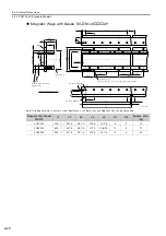
Mount the Magnetic
Way so that its edge
surfaces are flush
with the inner step.
Mount the Magnetic
Way so that its edge
surfaces are flush
with the inner step.
R: 0.5 max.
R: 1 max.
71.5
1 (at the factory)
103 max.(at the factory)
Mounting Section Details
Side-to-Side Cross Section
-0.1
-0.3
0
-0.2
0
-0.2
0
-0.2
+0.6
0
-0.1
-0.3
0
-0.2
0
-0.2
0
-0.2
+0.6
0
-0.1
-0.3
0
-0.2
0
-0.2
0
-0.2
+0.6
0