

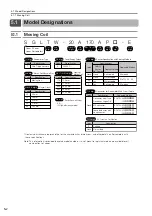
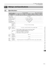


5.3 External Dimensions
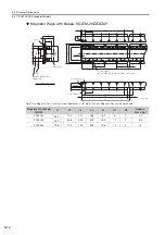
5.3.2 SGLTW-35: Standard Models
5
S
pecification
s
, Rating
s
, and Exter
nal Dimen
s
ion
s
of
SG
LT
S
ervomotor
s
5-13
5.3.2
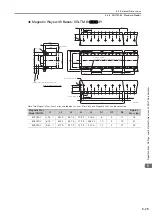
SGLTW-35: Standard Models
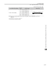
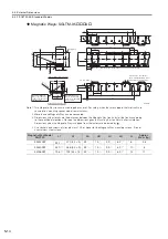
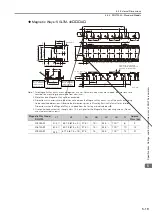
Moving Coils: SGLTW-35A
A
Moving Coil Model
SGLTW-
L1
L2
(L3)
N
Approx. Mass
[kg]
35A170A
170
144 (48
×
3)
(16)
8
3.7
35A320A
315
288 (48
×
6)
(17)
14
6.8
35A460A
460
432 (48
×
9)
(18)
20
10
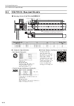
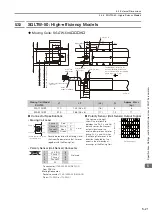
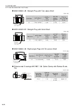
Connector Specifications
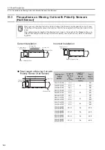
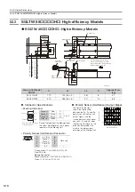
Polarity Sensor (Hall Sensor) Output Signal
•
Servomotor Connector
The figure on the right shows
the relationship between the
Su, Sv, and Sw polarity sen-
sor (hall sensor) output sig-
nals and the inverse power of
each motor phase Vu, Vv, and
Vw when the Moving Coil
moves in the direction indi-
cated by the arrow in the
dimensional drawings of the
Moving Coil.
Plug: 350779-1
Pins: 350218-3 or 350547-3 (No.1 to 3)
350654-1 or 350669-1 (No. 4)
From Tyco Electronics Japan G.K.
Mating Connector
Cap: 350780-1
Socket: 350537-3 or 350550-3
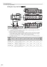
•
Polarity Sensor (Hall Sensor) Connector
Pin connector: 17JE-23090-02 (D8C)-CG
From DDK Ltd.
Mating Connector
Socket connector: 17JE-13090-02 (D8C)A-CG
Studs: 17L-002C or 17L-002C1
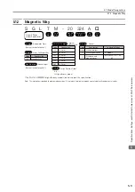
55
100
60
28
20
(70)
66
12
500
±
50
500
±
50
50
60
(70)
(15)
(L3)
L1
80
1
10
48
L2
(15)
N
×
M6
×
12
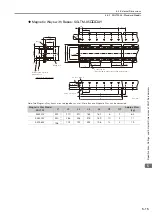
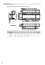
Magnetic Way
2
#4-40
UNC screws
(8.4 dia.)
(4.2 dia.)
Polarity sensor
(hall sensor)
63 min.
Unit: mm
100 min.
The Moving Coil moves in the direction
indicated by the arrow when current flows
in the following phase sequence: U, V, W.
(Gap: 1 without magnet cover)
(Gap: 0.8 with magnet cover)
(19 without magnet cover)
(19.2 with magnet cover)
Vu
Vv
Vw
Su
Sv
Sw
0
180
360
540
Inverse power (V)
Electrical angle (
°
)
1
2
3
4
1
Phase U
Red
2
Phase V
White
3
Phase W
Blue
4
FG
Green
9
6
5
1
1
+5 V (DC)
6
Not used
2
Phase U
7
3
Phase V
8
4
Phase W
9
5
0 V
−
−