


7.2 Installation Procedure
7.2.2 SGLF Servomotors (Models with F-type Iron Cores)
7
S
ervomotor In
s
tallation
7-9
6.
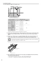
Remove the thin nonmagnetic sheet.
7.
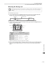
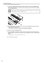
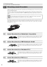
Use a nonmagnetic gap gauge to confirm that the gap between the Moving Coil and
Magnetic Way is 1
±
0.3 mm
*
at all locations. (We recommend a brass or stainless steel
gauge.)
*
If the magnet cover is in place, the gaps should be 0.8 ±0.3 mm
This concludes the procedure.
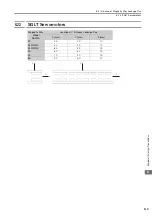
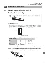
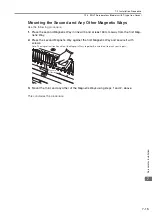
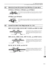
Mounting the Second and Any Other Magnetic Ways
Use the following procedure.
1.
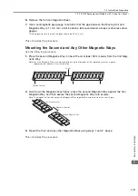
Place the second Magnetic Way in line with and at least 30 mm away from the first Mag-
netic Way.
Note: Face the Magnetic Ways in same orientation using the locations of the reference marks as a guide
(depressions of approx. 4 mm in diameter).
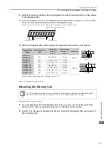
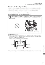
2.
Hold down the Magnetic Way tightly, press the second Magnetic Way against the first
Magnetic Way, and then secure the second Magnetic Way with screws.
Note: The magnetic attraction will pull the Magnetic Ways together. Be careful not to pinch your fingers.
3.
Mount the third and any other Magnetic Ways using steps 1 and 2, above.
This concludes the procedure.
30 mm
Reference mark
First Magnetic Way
Second Magnetic Way
Magnetic attraction