ELEC
–
+
6C13G11
Electrical systems
Checking the electrical components............................................................ 8-2
Port view.................................................................................................... 8-3
Bow view ................................................................................................... 8-4
Starboard view........................................................................................... 8-5
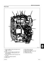
Top view .................................................................................................... 8-6
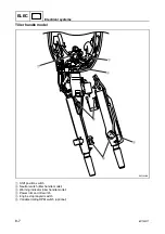
Tiller handle model .................................................................................... 8-7
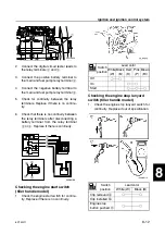
Checking the ignition spark ....................................................................... 8-8
Checking the spark plug wires................................................................... 8-8
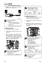
Checking the ignition coils ......................................................................... 8-8
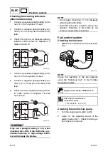
Checking the ECM..................................................................................... 8-9
Checking the pulser coil ............................................................................ 8-9
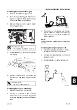
Checking the pulser coil air gap .............................................................. 8-10
Checking the sensor assembly................................................................ 8-10
Checking the oil pressure switch ............................................................. 8-10
Checking the cooling water temperature sensor ..................................... 8-11
Checking the shift position switch............................................................ 8-11
Checking the neutral switch (tiller handle model) .................................... 8-11
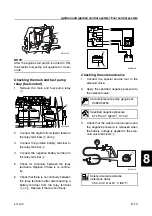
Checking the main and fuel pump relay (main control) ........................... 8-11
Checking the engine start switch (tiller handle model) ............................ 8-12
Checking the engine stop lanyard switch (tiller handle model)................ 8-12
Checking the warning indicators (tiller handle model) ............................. 8-13
Checking the injectors ............................................................................. 8-13
Checking the electric fuel pump .............................................................. 8-13
Checking the main and fuel pump relay (fuel control) ............................. 8-14
Checking the solenoid valve.................................................................... 8-14
Summary of Contents for F50F
Page 1: ...F50F FT50G F60C FT60D SERVICE MANUAL 6C1 28197 3G 11 290551 ...
Page 4: ......
Page 48: ...SPEC Specifications 2 25 6C13G11 MEMO ...
Page 190: ...LOWR Lower unit 6 47 6C13G11 Shimming FT50 FT60 6 ...
Page 195: ...6C13G11 6 52 1 2 3 4 5 6 7 8 9 MEMO Backlash FT50 FT60 ...
Page 221: ...6C13G11 7 24 1 2 3 4 5 6 7 8 9 Steering arm ...
Page 249: ...6C13G11 7 52 1 2 3 4 5 6 7 8 9 MEMO Power trim and tilt electrical system ...
Page 272: ...ELEC Electrical systems 8 21 6C13G11 MEMO ...
Page 301: ...6C13G11 i 5 1 2 3 4 5 6 7 8 9 Index MEMO ...
Page 303: ......
Page 304: ...YAMAHA MOTOR CO LTD Printed in the Netherlands Jul 2004 1 2 1 CR E_2 ...

