6C13G11
3-12
1
2
3
4
5
6
7
8
9
10. Adjust the position of the throttle cable
joint until its hole is aligned with the set
pin.
NOTE:
Pull the throttle cable towards the set pin to
remove any free play in the cable before
adjusting the position of the throttle cable
joint.
11. Connect the throttle cable joint, install the
clip, and then tighten the locknut.
WARNING
The throttle cable joint must be screwed
in a minimum of 8.0 mm (0.31 in)
f
.
12. Operate the throttle to check that the
throttle valves fully close and fully open,
and check that the throttle cam contacts
the fully closed stopper when the throttle
is in the fully closed position.
13. Check the throttle cable for smooth oper-
ation and, if necessary, repeat steps 1–
12.
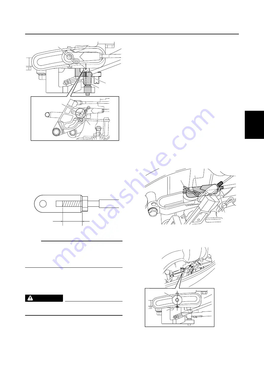
Checking the gear shift operation
1.
Check that the gear shift operates
smoothly when shifting it from neutral to
forward or reverse. Adjust the shift cable
length if necessary.
2.
Set the gear shift to the neutral position.
3.
Loosen the locknut
1
, remove the clip
2
, and then disconnect the shift cable
joint
3
.
4.
Align the center of the set pin
a
with the
alignment mark
b
on the bracket.
S6C13170
e
e
8
d
d
S6C13180
f
S6C13190
2
3
1
S6C13200
b
a
Summary of Contents for F50F
Page 1: ...F50F FT50G F60C FT60D SERVICE MANUAL 6C1 28197 3G 11 290551 ...
Page 4: ......
Page 48: ...SPEC Specifications 2 25 6C13G11 MEMO ...
Page 190: ...LOWR Lower unit 6 47 6C13G11 Shimming FT50 FT60 6 ...
Page 195: ...6C13G11 6 52 1 2 3 4 5 6 7 8 9 MEMO Backlash FT50 FT60 ...
Page 221: ...6C13G11 7 24 1 2 3 4 5 6 7 8 9 Steering arm ...
Page 249: ...6C13G11 7 52 1 2 3 4 5 6 7 8 9 MEMO Power trim and tilt electrical system ...
Page 272: ...ELEC Electrical systems 8 21 6C13G11 MEMO ...
Page 301: ...6C13G11 i 5 1 2 3 4 5 6 7 8 9 Index MEMO ...
Page 303: ......
Page 304: ...YAMAHA MOTOR CO LTD Printed in the Netherlands Jul 2004 1 2 1 CR E_2 ...


