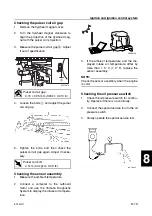
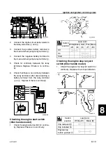
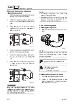
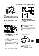
background image

ELEC

Electrical systems

+

8-7

6C13G11

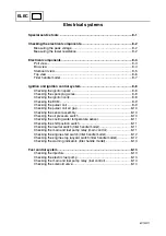
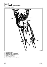
Tiller handle model

1

Shift position switch

2

Neutral switch (tiller handle model)

3

Warning indicator (tiller handle model)

4

Power trim and tilt switch

5

Engine stop lanyard switch

6

Variable trolling RPM switch (optional)

S6C18200

1

2

3

6

4

5

Summary of Contents for F50F

Page 1: ...F50F FT50G F60C FT60D SERVICE MANUAL 6C1 28197 3G 11 290551 ...

Page 2: ...ons and significant changes in specifications and procedures and these are incorporated in successive editions of this manual Important information 1 Particularly important information is distinguished in this manual by the following notations The Safety Alert Symbol means ATTENTION BECOME ALERT YOUR SAFETY IS INVOLVED WARNING Failure to follow WARNING instructions could result in severe injury or...

Page 3: ...nformation 1 GEN INFO Specifications 2 SPEC Periodic checks and adjustments 3 CHK ADJ Fuel system 4 FUEL Power unit 5 POWR Lower unit 6 LOWR Bracket unit 7 BRKT Electrical systems 8 ELEC Troubleshooting 9 TRBL SHTG Index ...

Page 4: ......

Page 5: ... Module 1 10 Variable trolling RPM switch optional 1 11 Propeller selection 1 12 Propeller size 1 12 Selection 1 12 Predelivery checks 1 13 Checking the fuel system 1 13 Checking the engine oil level 1 13 Checking the gear oil level 1 13 Checking the battery 1 13 Checking the outboard motor mounting height 1 14 Checking the remote control cables 1 14 Checking the steering system 1 14 Checking the ...

Page 6: ...Not reusable 6 Dowel pin 2 7 Bolt 4 M10 40 mm 8 Drain screw 1 9 Grommet 1 10 Bolt 1 M10 45 mm 11 Bolt 1 M8 60 mm 12 Thrust washer 1 13 Propeller 1 14 Washer 1 15 Washer 1 16 Cotter pin 1 Not reusable 17 Propeller nut 1 18 Trim tab 1 LOWR Lower unit 6 19 62Y5A11 Removing the drive shaft 1 Remove the drive shaft assembly and pinion and then pull out the forward gear Disassembling the drive shaft 1 I...

Page 7: ...ltage electric current Symbols 7 to C in an exploded diagram indicate the grade of lubricant and the lubrication point 7 Apply Yamaha 4 stroke motor oil 8 Apply gear oil 9 Apply water resistant grease Yamaha grease A 0 Apply molybdenum disulfide grease A Apply corrosion resistant grease Yamaha grease D B Apply low temperature resistant grease Yamaha grease C C Apply injector grease Symbols D to H ...

Page 8: ...sing an air compressor Protect your hands and feet by wearing pro tective gloves and safety shoes when neces sary Parts lubricants and sealants Use only genuine Yamaha parts lubricants and sealants or those recommended by Yamaha when servicing or repairing the out board motor Under normal conditions the lubricants men tioned in this manual should not harm or be hazardous to your skin However you s...

Page 9: ...when installing or assembling parts Disassembly and assembly 1 Use compressed air to remove dust and dirt during disassembly 2 Apply engine oil to the contact surfaces of moving parts before assembly 3 Install bearings with the manufacture identification mark in the direction indi cated in the installation procedure In addition be sure to lubricate the bearings liberally 4 Apply a thin coat of wat...

Page 10: ...hed to the port clamp bracket 1 Model name 2 Approved model code 3 Transom height 4 Serial number Hydro tilt model For Europe Tiller handle model For Oceania Model name Approved model code Starting serial No F50FED 6C1 1000001 F50FEHT F50FET FT50GET 6C2 1000001 F60CEHT 6C5 1000001 F60CET FT60DET 6C6 1000001 S6C11010 ...

Page 11: ...ssure regulator Solenoid valve Fuel cooler Aluminum rocker arm Electrical Compact electronic fuel injection system Self diagnosis system and Yamaha Diagnostic System Variable trolling RPM switch optional for tiller handle model Throttle position sensor with learning function adjustment free Compact charging system at low rpm Compact fuel injectors Fuel filter with water separator Clamp bracket upp...

Page 12: ...ischarged from the pressure regulator returns to the vapor separator after cooling down through the fuel cooler The fuel joint is used on the high pressure fuel hose to remove and or install the intake unit easily S6C11130 Fuel filter Optional Fuel tank Fuel cooler Pressure regulator Primer pump Fuel filter with water separator Fuel pump Mechanical Fuel filter Vapor separator Electric fuel pump Fu...

Page 13: ...ses are sucked into the combustion chambers causing a rich air and fuel mixture which is difficult to restart the engine So the solenoid valve has been used for better restarting engine while the engine is warm The solenoid valve stops the vapor gases not to return into the intake silencer 1 Fuel tank 2 Fuel filter 3 Fuel pump 4 Fuel cooler 5 Return fuel hose 6 Pressure regulator 7 Solenoid valve ...

Page 14: ... air and fuel mixture A F and igni tion timing Under various condition the ECM gives the best suitable engine operation In addition warning control fail safe control a self diagnosis function etc are equipped to increase reliability 1 Sensor assembly intake air temperature and intake air pressure 2 ECM 3 Throttle position sensor 4 Oil pressure switch 5 Cooling water temperature sensor 6 Pulser coi...

Page 15: ...8 1 23 6 20 21 7 26 8 25 9 11 24 45 13 Pulser coil Power source for sensors Throttle position sensor Intake air pressure sensor Cooling water pressure sensor Ground for sensors Intake air temperature sensor Cooling water temperature sensor Shift position switch Engine stop lanyard switch Oil pressure switch Variable trolling RPM switch UP Variable trolling RPM switch DOWN Ground for ECM Ground Bat...

Page 16: ...e engine rpm is controlled with 40 r min interval Pushing and holding the switch changes rpm continuously at 50 r min interval If engine rpm reaches to the ends of specified range the rpm is no longer changed CAUTION Do not modify the variable trolling RPM switch Modification such as wire extension disassembly etc can malfunction for the system and or damage the electrical components NOTE Variable...

Page 17: ...ated on a propeller blade on the propeller boss end a Propeller diameter in inches b Propeller pitch in inches c Propeller type propeller mark Selection When the engine speed is at the full throttle operating range 5 000 6 000 r min the ideal propeller for the boat is one that pro vides maximum performance in relation to boat speed and fuel consumption F50 F60 FT50 FT60 S69W1030 a b c S69W1040 a b...

Page 18: ...e engine oil is below the minimum level mark b add sufficient oil until the level is between a and b Checking the gear oil level 1 Check the gear oil level Checking the battery 1 Check the capacity electrolyte level and specified gravity of the battery 2 Check that the positive and negative bat tery leads are securely connected S6C11030 b a Recommended engine oil 4 stroke motor oil API SE SF SG SH...

Page 19: ... mounting height test run the outboard motor at differ ent heights 2 Check that the clamp brackets are secured with the clamp bolts Checking the remote control cables 1 Set the remote control lever or shift lever to the neutral position and fully close the throttle lever or throttle grip 2 Check that the set pin a is aligned with the alignment mark b 3 Check that the alignment mark c is aligned wi...

Page 20: ...r remote control model is shifted from forward or reverse to the fully open position a È Tiller handle model É Remote control model Checking the power trim and tilt system 1 Check that the outboard motor tilts up and down smoothly when operating the power trim and tilt unit 2 Check that there is no abnormal noise produced when the outboard motor is tilted up or down 3 Check that there is no interf...

Page 21: ...itch is turned to OFF È Tiller handle model É Remote control model 3 Check that the engine turns off when the engine stop lanyard switch is pushed or engine stop lanyard is pulled from the engine stop lanyard switch È Tiller handle model É Remote control model Checking the cooling water pilot hole 1 Check that cooling water is discharged from the cooling water pilot hole S6C11100 1 È S60V1070 OFF ...

Page 22: ...t flow in over the transom NOTE The test run is part of the break in operation Break in During the test run perform the break in operation in the following three stages 1 One hour a at 2 000 r min or at approxi mately half throttle 2 One hour b at 3 000 r min or 3 4 throttle and 1 minute out of every 10 at full throt tle 3 Eight hours c at any speed however avoid running at full speed for more tha...

Page 23: ...ations General specifications 2 1 Maintenance specification 2 5 Power unit 2 5 Lower unit 2 8 Electrical 2 9 Power unit 2 11 Lower unit 2 14 Electrical 2 15 Dimensions 2 17 Tightening torques 2 21 Specified torques 2 21 General torques 2 24 ...

Page 24: ...50 0 at 5 500 r min Full throttle operating range r min 5 000 6 000 Maximum fuel consumption L US gal lmp gal hr 18 5 4 89 4 07 at 6 000 r min Engine idle speed r min 700 800 Power unit Type In line 4 stroke SOHC 8 valves Cylinder quantity 4 Total displacement cm3 cu in 996 60 8 Bore stroke mm in 65 0 75 0 2 56 2 95 Compression ratio 9 50 Control system Remote control Tiller handle Remote control ...

Page 25: ...qt lmp qt 2 5 2 64 2 20 with oil filter replacement L US qt lmp qt 2 7 2 85 2 38 Gear oil type Hypoid gear oil Gear oil grade 2 API GL 4 SAE 90 Gear oil quantity cm3 US oz lmp oz 430 14 5 15 2 670 22 7 23 6 Bracket unit Trim angle at 12 boat transom Degree 4 to 20 Tilt up angle Degree 67 69 Steering angle Degree 40 40 Drive unit Gear shift positions F N R Gear ratio 1 85 13 24 2 31 13 30 Reduction...

Page 26: ...n Full throttle operating range r min 5 000 6 000 Maximum fuel consumption L US gal lmp gal hr 20 0 5 28 4 40 at 6 000 r min Engine idle speed r min 700 800 Power unit Type In line 4 stroke SOHC 8 valves Cylinder quantity 4 Total displacement cm3 cu in 996 60 8 Bore stroke mm in 65 0 75 0 2 56 2 95 Compression ratio 9 50 Control system Tiller handle Remote control Starting system Electric Fuel sys...

Page 27: ...L US qt lmp qt 2 5 2 64 2 20 with oil filter replacement L US qt lmp qt 2 7 2 85 2 38 Gear oil type Hypoid gear oil Gear oil grade 2 API GL 4 SAE 90 Gear oil quantity cm3 US oz lmp oz 430 14 5 15 2 670 22 7 23 6 Bracket unit Trim angle at 12 boat transom Degree 4 to 20 Tilt up angle Degree 69 Steering angle Degree 40 40 Drive unit Gear shift positions F N R Gear ratio 1 85 13 24 2 31 13 30 Reducti...

Page 28: ...Piston diameter D mm in 64 950 64 965 2 5571 2 5577 Measuring point H mm in 5 0 0 20 Piston clearance mm in 0 035 0 065 0 0014 0 0026 Piston pin boss bore mm in 15 974 15 985 0 6289 0 6293 Oversize piston diameter 1st mm in 65 200 65 215 2 5669 2 5675 2nd mm in 65 450 65 465 2 5768 2 5774 Piston pins Outside diameter mm in 15 965 15 970 0 6285 0 6287 Piston rings Top ring Dimension B mm in 1 17 1 ...

Page 29: ... in 36 935 36 955 1 4541 1 4549 Camshaft journal oil clearance mm in 0 045 0 090 0 0018 0 0035 Camshaft runout limit mm in 0 03 0 0012 Rocker arm shaft Rocker arm shaft outside diameter mm in 15 971 15 991 0 6288 0 6296 Rocker arms Rocker arm inside diameter mm in 16 000 16 018 0 6299 0 6306 Valves Valve clearance cold Intake mm in 0 20 0 05 0 008 0 002 Exhaust mm in 0 30 0 05 0 012 0 002 Head dia...

Page 30: ...e mm in 0 05 0 22 0 0020 0 0087 Crankpin oil clearance mm in 0 016 0 040 0 0006 0 0016 Big end bearing thickness Yellow mm in 1 500 1 504 0 0591 0 0592 Red mm in 1 496 1 500 0 0589 0 0591 Pink mm in 1 492 1 496 0 0587 0 0589 Green mm in 1 488 1 492 0 0586 0 0587 Crankshaft Crankshaft journal diameter mm in 42 984 43 000 1 6923 1 6929 Crankpin diameter mm in 32 984 33 000 1 2986 1 2992 Crankpin wid...

Page 31: ...ning temperature C F 58 62 136 144 Fully open temperature C F 70 158 Valve open lower limit mm in 3 0 0 12 Item Unit Model F50FED F50FEHT F50FET FT50GET Gear backlash Pinion to forward gear mm in 0 35 0 81 0 0138 0 0319 0 09 0 62 0 0035 0 0244 Pinion to reverse gear mm in 0 89 1 34 0 0350 0 0528 Pinion shims mm 0 10 0 12 0 15 0 18 0 30 0 40 0 50 Forward gear shims mm 0 10 0 12 0 15 0 18 0 30 0 40 ...

Page 32: ... 20 7 at 3 500 r min loaded V 32 0 Pulser coil resistance 2 W B W R Ω 396 594 Pulser coil air gap mm in 0 75 0 25 0 030 0 010 Throttle position sensor Output voltage P B V 0 8 1 2 at engine idle speed Sensor assembly resistance 2 at 20 C 68 F kΩ 5 4 6 6 at 80 C 176 F kΩ 0 282 0 382 Cooling water temperature sensor resistance 2 B Y B at 20 C 68 F kΩ 2 439 at 60 C 140 F kΩ 0 589 at 100 C 212 F kΩ 0 ...

Page 33: ...r min unloaded V 42 2 at 3 500 r min unloaded V 96 6 Stator coil resistance 1 at 20 C 68 F W W Ω 0 52 0 63 Rectifier Regulator output peak voltage R B at 1 500 r min unloaded V 13 0 at 3 500 r min unloaded V 13 0 Power trim and tilt system Trim sensor Setting resistance P B Ω 9 11 Resistance P B Ω 9 288 3 Fluid type ATF Dexron II Brushes Standard limit mm in 11 0 0 43 Wear limit mm in 4 5 0 18 Com...

Page 34: ... mm in 64 950 64 965 2 5571 2 5577 Measuring point H mm in 5 0 0 20 Piston clearance mm in 0 035 0 065 0 0014 0 0026 Piston pin boss bore mm in 15 974 15 985 0 6289 0 6293 Oversize piston diameter 1st mm in 65 200 65 215 2 5669 2 5675 2nd mm in 65 450 65 465 2 5768 2 5774 Piston pins Outside diameter mm in 15 965 15 970 0 6285 0 6287 Piston rings Top ring Dimension B mm in 1 17 1 19 0 0461 0 0469 ...

Page 35: ...4 mm in 36 935 36 955 1 4541 1 4549 Camshaft journal oil clearance mm in 0 045 0 090 0 0018 0 0035 Camshaft runout limit mm in 0 03 0 0012 Rocker arm shaft Rocker arm shaft outside diameter mm in 15 971 15 991 0 6288 0 6296 Rocker arms Rocker arm inside diameter mm in 16 000 16 018 0 6299 0 6306 Valves Valve clearance cold Intake mm in 0 20 0 05 0 008 0 002 Exhaust mm in 0 30 0 05 0 012 0 002 Head...

Page 36: ...rance mm in 0 05 0 22 0 0020 0 0087 Crankpin oil clearance mm in 0 016 0 040 0 0006 0 0016 Big end bearing thickness Yellow mm in 1 500 1 504 0 0591 0 0592 Red mm in 1 496 1 500 0 0589 0 0591 Pink mm in 1 492 1 496 0 0587 0 0589 Green mm in 1 488 1 492 0 0586 0 0587 Crankshaft Crankshaft journal diameter mm in 42 984 43 000 1 6923 1 6929 Crankpin diameter mm in 32 984 33 000 1 2986 1 2992 Crankpin...

Page 37: ...tat Opening temperature C F 58 62 136 144 Fully open temperature C F 70 158 Valve open lower limit mm in 3 0 0 12 Item Unit Model F60CEHT F60CET FT60DET Gear backlash Pinion to forward gear mm in 0 35 0 81 0 0138 0 0319 0 09 0 62 0 0035 0 0244 Pinion to reverse gear mm in 0 89 1 34 0 0350 0 0528 Pinion shims mm 0 10 0 12 0 15 0 18 0 30 0 40 0 50 Forward gear shims mm 0 10 0 12 0 15 0 18 0 30 0 40 ...

Page 38: ... 7 at 3 500 r min loaded V 32 0 Pulser coil resistance 2 W B W R Ω 396 594 Pulser coil air gap mm in 0 75 0 25 0 030 0 010 Throttle position sensor Output voltage P B V 0 8 1 2 at engine idle speed Sensor assembly resistance 2 at 20 C 68 F kΩ 5 4 6 6 at 80 C 176 F kΩ 0 282 0 382 Cooling water temperature sensor resistance 2 B Y B at 20 C 68 F kΩ 2 439 at 60 C 140 F kΩ 0 589 at 100 C 212 F kΩ 0 193...

Page 39: ...500 r min unloaded V 42 2 at 3 500 r min unloaded V 96 6 Stator coil resistance 1 at 20 C 68 F W W Ω 0 52 0 63 Rectifier Regulator output peak voltage R B at 1 500 r min unloaded V 13 0 at 3 500 r min unloaded V 13 0 Power trim and tilt system Trim sensor Setting resistance P B Ω 9 11 Resistance P B Ω 9 288 3 Fluid type ATF Dexron II Brushes Standard limit mm in 11 0 0 43 Wear limit mm in 4 5 0 18...

Page 40: ...ower trim and tilt model S6C12030 mm in A 6 3 B 6 5 4 0 192 7 6 188 7 4 360 14 2 192 7 6 870 34 3 527 20 7 A 762 30 0 B 759 29 9 354 13 9 49 1 9 A 25 1 0 B 22 0 9 175 6 9 4 A 682 26 9 B 708 27 9 533 21 0 24 0 9 A 406 16 0 B 417 16 4 A 930 36 6 B 932 36 7 122 4 8 62 2 4 584 23 0 97 3 8 12 545 21 5 A 148 5 8 B 147 5 8 ...

Page 41: ...l 1 For Oceania S6C12020E mm in 4 0 192 7 6 188 7 4 360 14 2 192 7 6 759 29 9 645 25 4 354 14 0 49 1 9 37 1 5 175 6 9 4 708 27 9 533 21 0 24 0 9 755 29 7 417 16 4 226 8 9 62 2 4 584 23 0 164 6 5 97 3 8 12 545 21 5 932 36 7 758 29 8 124 4 9 6 5 527 20 7 870 343 Maintenance specification ...

Page 42: ...mm in 4 0 192 7 6 188 7 4 360 14 2 192 7 6 759 29 9 354 13 9 62 2 4 22 0 9 191 7 5 4 561 22 1 24 0 9 417 16 4 147 5 8 122 4 8 62 2 4 584 23 0 545 21 5 L 996 39 2 X 1 099 43 3 L 530 20 9 X 644 25 4 L 746 29 4 X 812 32 0 L 98 3 9 X 114 4 5 L 910 35 8 X 1 024 40 3 12 6 5 ...

Page 43: ...3G11 2 20 1 2 3 4 5 6 7 8 9 Clamp bracket S6C12070 mm in 13 0 5 180 7 1 163 5 6 4 254 0 10 0 55 5 2 2 350 13 8 163 5 6 4 126 5 0 126 5 0 180 7 1 13 0 5 50 8 2 0 18 5 0 7 70 5 2 78 Maintenance specification ...

Page 44: ...wer unit mounting bolt M8 27 2 7 20 0 Shift position switch screw M4 2 0 2 1 5 Stator coil bracket bolt M6 4 0 4 3 0 Pulser coil bolt M5 4 0 4 3 0 Flywheel magnet nut M20 157 15 7 115 8 Starter motor bolt M8 29 2 9 21 4 Starter motor terminal nut M8 9 0 9 6 6 Starter relay lead bolt M6 4 0 4 3 0 Starter motor lead screw M4 2 0 2 1 5 Starter relay holder screw M6 3 0 3 2 2 Main and fuel pump relay ...

Page 45: ...cting rod cap bolt 1st 6 0 6 4 4 2nd 17 1 7 12 5 Lower unit F50 F60 Gear oil drain screw 9 0 9 6 6 Gear oil check screw 9 0 9 6 6 Lower case mounting bolt M10 39 3 9 28 8 Propeller nut M16 34 3 4 25 1 Ring nut 103 10 3 76 0 Cooling water inlet cover screw 4 0 4 3 0 Pinion nut M16 74 7 4 54 6 Propeller shaft housing bolt M8 16 1 6 11 8 Lower unit FT50 FT60 Gear oil drain screw 9 0 9 6 6 Gear oil ch...

Page 46: ...6 10 1 0 7 4 Exhaust manifold bolt M6 10 1 0 7 4 Oil pan bolt M8 27 2 7 20 0 Oil strainer bolt M6 10 1 0 7 4 Upper mounting nut M8 24 2 4 17 7 Self locking nut 22 2 2 16 2 Grease nipple 3 0 3 2 2 Power trim and tilt unit PTT motor bolt M5 4 0 4 3 0 Reservoir cap 7 0 7 5 2 Manual valve 2 0 2 1 5 Gear pump bolt M5 5 0 5 3 7 Lever bolt M3 3 0 3 2 2 Relief valve seat cap bolt M4 4 0 4 3 0 M5 5 0 5 3 7...

Page 47: ...ons of this man ual To avoid warpage tighten multi fastener assemblies in a crisscross fashion and pro gressive stages until the specified torque is reached Unless otherwise specified torque specifications require clean dry threads Components should be at room temperature Nut A Bolt B General torque specifications N m kgf m ft lb 8 mm M5 5 0 5 3 6 10 mm M6 8 0 8 5 8 12 mm M8 18 1 8 13 14 mm M10 36...

Page 48: ...SPEC Specifications 2 25 6C13G11 MEMO ...

Page 49: ... Replacing the timing belt 3 6 Checking the spark plugs 3 8 Checking the thermostat 3 9 Checking the cooling water passage 3 10 Control system 3 10 Checking the engine idle speed 3 10 Adjusting the throttle link and throttle cable 3 10 Checking the gear shift operation 3 12 Bracket unit 3 13 Checking the power trim and tilt operation 3 13 Checking the hydro tilt unit operation 3 13 Checking the po...

Page 50: ...eriodic checks and adjustments 3 1 6C13G11 Special service tools 3 Digital tachometer 90890 06760 Leakage tester 90890 06840 Oil filter wrench 90890 01426 Flywheel holder 90890 06522 Flywheel puller 90890 06521 ...

Page 51: ...op cowling Check 3 3 Fuel filter can be disassembled Check replace 3 3 Fuel system Check 3 3 Fuel tank Yamaha portable tank Check clean Gear oil Change 3 14 Lubrication points Lubricate 3 18 Engine idle speed EFI models Check adjust 3 10 Power trim and tilt unit Check 3 13 Propeller and cotter pin Check replace 3 16 Shift link shift cable Check adjust 3 12 Thermostat Check 3 9 Throttle link thrott...

Page 52: ...s and fuel joint for leaks Replace if necessary Also check the fuel filter 1 fuel pump 2 strainer 3 and fuel cooler 4 for leaks or deterioration Replace if necessary 3 Check the high pressure fuel hose con nections for leaks Replace if necessary Also check the vapor separator 5 fuel rail 6 fuel injectors 7 and pressure regulator 8 for leaks or deterioration Replace if necessary Checking the fuel f...

Page 53: ...ert the tube of the oil changer 2 into the dipstick hole 3 4 Operate the oil changer to extract the oil NOTE Be sure to clean up any oil spills 5 Pour the specified amount of the recom mended engine oil into the oil filler hole 6 Install the oil filler cap and oil dipstick and then start the engine and warm it up for 5 minutes 7 Turn the engine off and then check the oil level and correct it if ne...

Page 54: ...placing the oil filter 1 Extract the engine oil with an oil changer or drain it 2 Place a rag under the oil filter and then remove the oil filter using the oil filter wrench 1 NOTE Wait more than 5 minutes after turning the engine off to replace the oil filter Be sure to clean up any oil spills 3 Apply a thin coat of engine oil to the O ring of the new oil filter 4 Install the oil filter and then ...

Page 55: ...rn the flywheel magnet clockwise to transfer the slack of the timing belt from port to starboard and then lightly hold the flywheel magnet in place 5 Slightly push the timing belt with your fin ger between the drive gear and driven gear and then measure the belt slack Replace the timing belt if above specifi cation Replacing the timing belt CAUTION Do not turn the flywheel magnet counter clockwise...

Page 56: ...omes off the tapered portion of the crankshaft 5 Disconnect the stator coil coupler and pulser coil coupler and remove the stator coil assembly 1 6 Remove the solenoid valve and then remove the timing belt 2 from the driven sprocket then from the drive sprocket CAUTION Do not turn the drive sprocket or the driven sprocket when the timing belt is not installed Otherwise the piston and valves will i...

Page 57: ...10 Install the solenoid valve and stator coil assembly and connect the stator coil coupler and pulser coil coupler 11 Install the Woodruff key then the fly wheel magnet CAUTION Apply force in the direction of the arrows shown to prevent the flywheel holder from slipping off easily NOTE Apply engine oil to the flywheel magnet nut before installation 12 Adjust the pulser coil air gap NOTE For adjust...

Page 58: ... specification 5 Install the spark plugs tighten them fin ger tight then to the specified torque using a spark plug wrench Checking the thermostat 1 Remove the cover 1 gasket and ther mostat 2 2 Suspend the thermostat in a container of water 3 Place a thermometer in the water and slowly heat the water 4 Check the thermostat valve opening at the specified water temperatures Replace if out of specif...

Page 59: ... 1 Start the engine and warm it up for 5 min utes 2 Attach the special service tool to spark plug wire 1 1 and then check the engine idle speed Adjusting the throttle link and throttle cable 1 Set the remote control lever to the neu tral position and fully close the throttle lever Set the throttle grip to the fully closed position 2 Disconnect the throttle link rod from the throttle body and the t...

Page 60: ... throttle control lever to the throttle cam as shown and then adjust the position of the throttle link rod until the joint 3 of the throttle link rod is aligned with the joint 4 of the control lever 7 Connect the throttle link rod to the throttle link and then tighten the locknut 8 Loosen the locknut 5 remove the clip 6 and then disconnect the throttle cable joint 7 9 Adjust the throttle cam 8 unt...

Page 61: ...lves fully close and fully open and check that the throttle cam contacts the fully closed stopper when the throttle is in the fully closed position 13 Check the throttle cable for smooth oper ation and if necessary repeat steps 1 12 Checking the gear shift operation 1 Check that the gear shift operates smoothly when shifting it from neutral to forward or reverse Adjust the shift cable length if ne...

Page 62: ...wer trim and tilt fluid level if necessary NOTE Be sure to listen to the winding sound of the power trim and tilt motor for smooth opera tion 2 Fully tilt the outboard motor up and then support it with the tilt stop lever 1 to check the lock mechanism of the lever Checking the hydro tilt unit operation 1 Fully tilt the outboard motor up and down a few times and check the entire tilt range for smoo...

Page 63: ...hould overflow out of the filler hole when the reservoir cap is removed 3 If necessary add sufficient fluid of the recommended type until it overflows out of the filler hole 4 Install the reservoir cap and then tighten it to the specified torque Lower unit 3 Checking the gear oil level 1 Fully tilt the outboard motor down 2 Remove the check screw 1 and then check the gear oil level in the lower ca...

Page 64: ...se if necessary 4 Insert a gear oil tube or gear oil pump into the drain hole and slowly fill the gear oil until oil flows out of the check hole and no air bubbles are visible 5 Install the check screw and quickly install the drain screw and then tighten them to the specified torque Checking the lower unit for air leakage 1 Remove the check screw 1 and then install the special service tool Recomme...

Page 65: ...ing the tester from the lower unit 3 If pressure drops below specification check the drive shaft and propeller shaft oil seals for damage Checking the propeller 1 Check the propeller blades and splines for cracks damage or wear Replace if necessary General 3 Checking the anodes 1 Check the anodes and trim tab for scales grease or oil Clean if necessary Leakage tester 90890 06840 Lower unit holding...

Page 66: ...asures Avoid bodily contact with electrolyte as it can cause severe burns or permanent eye injury Wear protective eye gear when handling or working near batteries Antidote EXTERNAL SKIN Wash with water EYES Flush with water for 15 minutes and get immediate medical attention Antidote INTERNAL Drink large quantities of water or milk followed with milk of magnesia beaten egg or vegetable oil Get imme...

Page 67: ...7 8 9 Lubricating the outboard motor 1 Apply water resistant grease to the areas shown NOTE Apply grease to the grease nipple until it flows from the bushings a S6C13270 A A S6C13290 A A A A a S6C17360 É S6C17540 A A a General ...

Page 68: ...CHK ADJ Periodic checks and adjustments 3 19 6C13G11 2 Apply low temperature resistant grease to the area shown 3 Apply corrosion resistant grease to the area shown S6C13280 C ...

Page 69: ...g the fuel pump 4 7 Checking the fuel joint 4 7 Intake manifold 4 8 Checking the throttle position sensor 4 11 Installing the throttle position sensor 4 11 Checking the idle speed control 4 11 Vapor separator 4 12 Disconnecting the quick connector 4 16 Measuring the fuel pressure 4 16 Checking the pressure regulator 4 17 Draining the fuel 4 18 Disassembling the vapor separator 4 18 Checking the va...

Page 70: ...FUEL Fuel system 4 1 6C13G11 Special service tools 4 Vacuum pressure pump gauge set 90890 06756 Fuel pressure gauge 90890 06786 Fuel pressure gauge adapter B 90890 06942 ...

Page 71: ...3 Fuel hose fuel filter to fuel pump 4 Fuel hose fuel pump to strainer 5 Fuel hose strainer to vapor separator 6 High pressure fuel hose vapor separator to fuel rail 7 Fuel hose pressure regulator to fuel cooler 8 Fuel hose fuel cooler to vapor separator 4 5 3 2 7 6 5 8 S6C14010 3 1 2 Special service tools Hose routing ...

Page 72: ...3 Cooling water pilot hose fuel joint to upper case 4 Flushing hose hose joint to fuel joint 5 Cooling water pilot hose fuel joint to water outlet joint 6 Cooling water pilot hose fuel cooler to fuel joint 7 Cooling water pilot hose water outlet joint to water outlet 8 Cooling water pilot hose water outlet joint to exhaust cover S6C14340 1 6 2 3 4 5 3 6 4 5 7 8 ...

Page 73: ...trainer 1 6 O ring 1 Not reusable 7 Screw 1 ø6 14 mm 8 Bolt 1 M8 16 mm 9 Nut 1 10 Bracket 1 11 Fuel filter assembly 1 12 O ring 1 Not reusable 13 Fuel filter element 1 14 O ring 1 Not reusable 15 Float 1 16 Cup 1 17 Clamp 4 S6C14320 9 10 8 11 1 6 3 2 4 5 T R 3 N m 0 3 kgf m 2 2 ft Ib 12 13 14 15 16 7 2 17 17 17 17 Hose routing Fuel filter and fuel pump ...

Page 74: ...6C13G11 4 No Part name Q ty Remarks 1 Screw 4 ø5 43 mm 2 Cover 1 3 Seal 1 Not reusable 4 Fuel pump body 2 assembly 1 5 Diaphragm 1 6 Pin 1 7 Spring 1 8 Fuel pump body 1 1 9 Nut 4 10 Spring 1 11 Plunger 1 12 Spring washer 4 ...

Page 75: ...akage Disas semble the fuel pump if necessary NOTE Assemble the fuel pump valve to the fuel pump body and moisten the inside of the fuel pump with gasoline to ensure a good seal Disassembling the fuel pump 1 Disassemble the fuel pump 2 Push down on the plunger and the dia phragm turn fuel pump body 1 1 approximately 90 to a position where the pin 2 can be removed easily and then remove the pin 3 S...

Page 76: ...nd the dia phragm and then install the pin 1 3 Turn fuel pump body 1 2 approximately 90 and then push down on the plunger several times to make sure that the pin does not come out NOTE Make sure that the gasket and diaphragm are kept in place through the assembly process Checking the fuel joint 1 Check the fuel hose connector for cracks or damage 2 Connect the special service tool to the fuel hose...

Page 77: ...hose 1 2 Holder 1 3 Hose 1 4 Bolt 2 M6 35 mm 5 Bolt 3 M6 45 mm 6 Bolt 5 M8 40 mm 7 Intake manifold assembly 1 8 Cooling water pilot hose 1 9 Pressure regulator hose 1 10 Dowel 2 11 Plastic tie 1 Not reusable S6C14100 1 3 2 9 4 10 6 7 8 10 11 5 Fuel filter and fuel pump Intake manifold ...

Page 78: ... Sensor assembly 1 9 O ring 1 Not reusable 10 Collar 2 11 Grommet 2 12 Intake silencer 1 13 Screw 2 14 Throttle position sensor 1 15 O ring 1 Not reusable 16 Bolt 3 M6 16 mm 17 Throttle body assembly 1 S6C14110 T R 9 N m 0 9 kgf m 6 6 ft Ib T R 4 N m 0 4 kgf m 3 0 ft Ib T R 9 N m 0 9 kgf m 6 6 ft Ib 24 23 1 22 21 2 T R 4 N m 0 4 kgf m 3 0 ft Ib 4 5 3 6 9 8 7 13 14 15 18 19 17 16 12 11 10 20 16 4 2...

Page 79: ...ke manifold 1 21 Fuel injector 4 22 O ring set 4 Not reusable 23 Clip 2 24 Bolt 2 M6 38 mm S6C14110 T R 9 N m 0 9 kgf m 6 6 ft Ib T R 4 N m 0 4 kgf m 3 0 ft Ib T R 9 N m 0 9 kgf m 6 6 ft Ib 24 23 1 22 21 2 T R 4 N m 0 4 kgf m 3 0 ft Ib 4 5 3 6 9 8 7 13 14 15 18 19 17 16 12 11 10 20 16 4 24 Intake manifold ...

Page 80: ... voltage is within specification NOTE If the throttle position sensor output voltage is out of specification reinstall the throttle position sensor Measure the throttle position sensor output voltage using the Yamaha Diagnostic Sys tem Do not turn the throttle stop screw a Checking the idle speed control 1 Check the operation of the idle speed control using the Yamaha Diagnostic System Throttle po...

Page 81: ...or separator 4 No Part name Q ty Remarks 1 Vapor separator 1 2 Collar 3 3 Grommet 3 4 Bolt 3 M6 30 mm 5 Cooling water pilot hose 1 6 Bolt 1 M6 15 mm 7 Corrugated tube 1 S6C14130 6 3 2 4 1 5 4 4 3 3 7 2 2 Intake manifold Vapor separator ...

Page 82: ... assembly 1 10 Gasket 1 Not reusable 11 Hose 1 12 Hose 1 13 Screw 2 ø6 14 mm 14 Fuel cooler 1 15 Hose 1 16 Fuel hose 1 17 Joint screw 1 S6C14140 WATER FUEL WATER T R 1 5 N m 0 15 kgf m 1 1 ft Ib T R 3 N m 0 3 kgf m 2 2 ft Ib T R 4 N m 0 4 kgf m 3 0 ft Ib T R 3 N m 0 3 kgf m 2 2 ft Ib 4 5 3 2 1 27 26 25 23 24 22 8 10 6 13 14 15 11 12 21 20 19 18 17 16 7 9 28 28 ...

Page 83: ...hamber 1 23 Fuel pump damper 1 24 High pressure fuel hose 1 25 Clamp 1 26 Hose 1 27 Solenoid valve 1 28 Clamp 2 S6C14140 WATER FUEL WATER T R 1 5 N m 0 15 kgf m 1 1 ft Ib T R 3 N m 0 3 kgf m 2 2 ft Ib T R 4 N m 0 4 kgf m 3 0 ft Ib T R 3 N m 0 3 kgf m 2 2 ft Ib 4 5 3 2 1 27 26 25 23 24 22 8 10 6 13 14 15 11 12 21 20 19 18 17 16 7 9 28 28 Vapor separator ...

Page 84: ...1 Not reusable 7 Electric fuel pump 1 8 Grommet 1 9 Collar 1 10 Filter 1 11 Screw 2 ø4 6 mm 12 Wiring harness 1 13 Float 1 14 Needle valve 1 15 Pin 1 Not reusable 16 Clip 1 Not reusable S6C14360 3 1 7 9 8 2 4 6 15 11 11 11 10 13 14 12 5 T R 2 N m 0 2 kgf m 1 5 ft Ib T R 2 N m 0 2 kgf m 1 5 ft Ib T R 4 N m 0 4 kgf m 3 0 ft Ib T R 5 N m 0 5 kgf m 3 7 ft Ib 16 ...

Page 85: ...isconnect the quick connector 3 from the fuel rail 4 directly WARNING Always reduce the fuel pressure in the fuel line before servicing the line or the fuel pipe If the fuel pressure is not released pressurized fuel could spray out Measuring the fuel pressure 1 Disconnect the quick connector from the fuel rail NOTE Before disconnecting the quick connector release the fuel pressure 2 Connect the sp...

Page 86: ...e make sure that the drain screw is tight ened securely Checking the pressure regulator 1 Remove the cap 2 Disconnect the quick connector from the fuel rail NOTE Before disconnecting the quick connector release the fuel pressure 3 Connect the special service tools as shown 4 Disconnect the pressure regulator hose and then connect the special service tools to the pressure regulator WARNING When con...

Page 87: ...nd then press in the valve a using a thin screwdriver to release the fuel pressure WARNING Always reduce the fuel pressure in the high pressure fuel line before servicing the line or the vapor separator If the fuel pressure is not released pressurized fuel may spray out 3 Place a container under the vapor sepa rator drain hose and then loosen the drain screw 2 4 Drain the fuel from the vapor separ...

Page 88: ...w one Install the float pin in the direction of the arrow a shown Install the float pin with its tapered end towards the punch mark b on the vapor separator cover 5 Check the float height c as shown Adjust the float height if out of specifica tion 6 Check the float height d as shown Adjust the float height if out of specifica tion NOTE The float should be resting on the needle valve but not compre...

Page 89: ...ation NOTE When adjusting the float height do not bend the lever e Assembling the vapor separator 1 Install the float chamber 2 Install all parts removed during dissas embly NOTE Be sure to connect and route the hoses cor rectly Float height b 46 6 1 0 mm 1 83 0 04 in Float height d 35 0 1 0 mm 1 38 0 04 in Vapor separator ...

Page 90: ...head 5 19 Removing the cylinder head 5 23 Checking the valve springs 5 24 Checking the valves 5 24 Checking the valve guides 5 25 Replacing the valve guides 5 25 Checking the valve seat 5 26 Refacing the valve seat 5 27 Checking the rocker arms and rocker arm shaft 5 29 Checking the camshaft 5 29 Checking the cylinder head 5 30 Checking the oil pump 5 31 Installing the valves 5 31 Installing the c...

Page 91: ...ston ring side clearance 5 41 Checking the piston pin boss bore 5 41 Checking the piston pin 5 41 Checking the connecting rod small end inside diameter 5 41 Checking the connecting rod big end side clearance 5 41 Checking the crankshaft 5 42 Checking the crankpin oil clearance 5 42 Selecting the connecting rod bearing 5 43 Checking the crankshaft journal oil clearance 5 44 Selecting the main beari...

Page 92: ...90890 06522 Flywheel puller 90890 06521 Crankshaft holder 18 90890 06562 Valve spring compressor 90890 04019 Valve spring compressor attachment 90890 06320 Valve guide remover installer 90890 06801 Valve guide installer 90890 06810 Valve guide reamer 90890 06804 Valve seat cutter holder 90890 06316 ...

Page 93: ... 5 6 7 8 9 Valve seat cutter 90890 06312 90890 06315 90890 06323 90890 06327 90890 06328 90890 06555 Bearing outer race attachment 90890 06626 Oil filter wrench 90890 01426 Piston slider 90890 06529 Special service tools ...

Page 94: ...again NOTE If the compression pressure increases check the pistons and piston rings for wear Replace if necessary If the compression pressure does not increase check the valve clearance valves valve seat cylinder sleeve cylinder head gasket and cylinder head Adjust or replace if necessary Checking the oil pressure 1 Place a rag under the oil pressure switch 2 Remove the oil pressure switch and the...

Page 95: ...cylinder head cover 4 4 Turn the flywheel magnet clockwise and align the 1 mark a on the driven sprocket with the mark b on the cyl inder head 5 Check the intake valve clearance for cyl inders 1 and 2 and the exhaust valve clearance for cylinders 1 and 3 Adjust if out of specification 6 Turn the flywheel magnet clockwise and align the 4 mark c on the driven sprocket with the mark b on the cyl inde...

Page 96: ...e the valve clearance turn the adjusting screw clockwise To increase the valve clearance turn the adjusting screw counterclockwise 9 Tighten the rocker arm locknut to the specified torque and then check the valve clearance again Adjust if neces sary 10 Install the cylinder head cover fuel pump fuel filter spark plugs spark plug caps blowby hose and flywheel magnet cover Valve clearance cold Intake...

Page 97: ... 1 3 Gasket 1 Not reusable 4 Dowel 2 5 Bolt 2 M6 16 mm 6 Bolt 8 M8 80 mm 7 Apron 1 8 Screw 2 ø6 24 mm 9 Nut 2 10 Flywheel magnet cover 1 11 Grommet 2 12 Neutral switch 1 Tiller handle model 13 Shift position switch 1 14 Bolt 2 M6 20 mm 15 Screw 2 ø4 16 mm 16 Plate 1 17 Collar 1 Power unit ...

Page 98: ...1 5 No Part name Q ty Remarks 1 Nut 1 2 Washer 1 3 Flywheel magnet 1 4 Bolt 3 M6 30 mm 5 Stator coil 1 6 Stator coil bracket 1 7 Bolt 4 M6 30 mm 8 Collar 2 9 Pulser coil 1 10 Bolt 2 M5 12 mm 11 Woodruff key 1 12 Bolt 1 M6 20 mm ...

Page 99: ... 5 6 7 8 9 5 No Part name Q ty Remarks 1 Timing belt 1 2 Nut 1 Width across flats 41 mm 1 6 in 3 Retaining plate 1 4 Drive sprocket 1 5 Bolt 1 M10 35 mm 6 Washer 1 7 Driven sprocket 1 8 Dowel 1 9 Woodruff key 1 Power unit ...

Page 100: ...egulator 1 2 Bolt 2 M6 25 mm 3 Spark plug 4 4 Spark plug wire 4 5 Holder 1 6 Ignition coil 2 7 Bolt 4 M6 30 mm 8 Holder 2 9 Bracket 1 10 Bracket 1 11 Cover 1 12 Holder 1 S6C15050 T R 17 N m 1 7 kgf m 12 5 ft Ib T R 7 N m 0 7 kgf m 5 2 ft Ib 10 7 7 9 8 6 5 4 3 2 1 12 11 2 ...

Page 101: ...r relay 1 6 Bolt 2 M6 10 mm 7 Cap 2 8 Holder 1 9 Screw 1 ø6 19 mm 10 Fuse 1 30 A 11 Cap 1 12 Terminal 1 13 Nut 1 14 Cap 1 S6C15040 T R 29 N m 2 9 kgf m 21 4 ft Ib T R 2 N m 0 2 kgf m 1 5 ft Ib T R 3 N m 0 3 kgf m 2 2 ft Ib T R 9 N m 0 9 kgf m 6 6 ft Ib T R 4 N m 0 4 kgf m 3 0 ft Ib 13 14 5 8 10 11 9 7 6 12 2 4 1 3 2 2 Power unit ...

Page 102: ...lt 8 M6 28 mm 9 Grommet 8 10 Collar 8 11 Screw 1 ø6 19 mm 12 Bolt 2 M6 20 mm 13 Screw 4 ø6 55 mm 14 Bolt 2 M8 35 mm 15 Nut 1 16 Bolt 1 M6 20 mm 17 Engine hanger 1 S6C15060 T R 3 N m 0 3 kgf m 2 2 ft Ib T R 4 N m 0 4 kgf m 3 0 ft Ib T R 3 N m 0 3 kgf m 2 2 ft Ib 16 18 19 17 20 15 3 8 9 10 11 4 14 1 21 23 22 24 25 29 30 28 7 2 10 9 8 12 33 32 31 13 34 6 5 27 26 12 28 8 10 9 9 10 8 8 10 9 ...

Page 103: ... 20 mm 26 Fuse 3 20 A 27 Cap 3 28 Bolt 2 M6 14 mm 29 Bolt 1 M6 14 mm 30 Screw 1 ø6 19 mm 31 Cap 2 32 Nut 2 33 Washer 2 34 Plastic tie 1 Not reusable S6C15060 T R 3 N m 0 3 kgf m 2 2 ft Ib T R 4 N m 0 4 kgf m 3 0 ft Ib T R 3 N m 0 3 kgf m 2 2 ft Ib 16 18 19 17 20 15 3 8 9 10 11 4 14 1 21 23 22 24 25 29 30 28 7 2 10 9 8 12 33 32 31 13 34 6 5 27 26 12 28 8 10 9 9 10 8 8 10 9 Power unit ...

Page 104: ...ol lever 1 3 Bracket 1 4 Lever 1 5 Washer 1 6 Bushing 1 7 Clip 1 8 Bolt 2 M6 25 mm 9 Bolt 1 M6 35 mm 10 Collar 1 11 Wave washer 1 12 Cotter pin 1 Not reusable 13 Throttle cam roller 1 14 Bolt 1 M6 35 mm 15 Spring 1 16 Collar 1 S6C15070 A A A A A A A A 4 8 3 5 6 7 16 15 2 14 13 12 1 11 10 9 8 ...

Page 105: ...leads 1 and main switch coupler 2 3 Disconnect the PTT switch coupler 3 4 Disconnect the warning indicator cou plers 4 tiller handle model 5 Disconnect the throttle cable 5 shift cable 6 throttle link rod 7 and shift lever 8 6 Remove the oil dipstick 9 7 Remove the shift rod bolts 0 8 Disconnect the cooling water pilot hose flushing hose and fuel hose 9 Remove the apron A 1 S6C15200 2 S6C15210 3 S...

Page 106: ...nkshaft end until the fly wheel magnet comes off the tapered portion of the crankshaft Removing the timing belt and sprockets CAUTION Do not turn the drive sprocket counter clockwise otherwise the valve system may be damaged 1 Turn the drive sprocket clockwise and align the mark a on the retaining plate with the mark b on the cylin der block and check that the 1 mark c on the driven sprocket is al...

Page 107: ...nterfere with each other and be damaged 4 Loosen the driven sprocket bolt 5 and remove the driven sprocket 6 NOTE Make sure that the camshaft does not crank when loosening the driven sprocket bolt 5 Remove the nut retaining plate 7 drive sprocket 8 and Woodruff key 9 Checking the timing belt and sprockets 1 Check the interior and exterior of the tim ing belt for cracks damage or wear Replace if ne...

Page 108: ...driven sprocket 1 is aligned with the mark b on the cylinder head and then tighten the bolt 2 to the specified torque 2 Install the Woodruff key 3 drive sprocket 4 retaining plate 5 and nut 6 and then tighten the nut 3 Check that the mark c on the retain ing plate is aligned with the mark d on the cylinder block 4 Install the timing belt 7 to the drive sprocket then onto the driven sprocket with i...

Page 109: ...1 0 in otherwise it can be dam aged Do not get oil or grease on the timing belt 5 Turn the drive sprocket clockwise two turns and then check that the alignment marks are aligned 6 Tighten the drive sprocket nut to the specified torque NOTE Use a deep socket 8 for this procedure Crankshaft holder 18 9 90890 06562 T R Drive sprocket nut 140 N m 14 0 kgf m 103 3 ft lb Power unit ...

Page 110: ...inder head 1 2 Screw 6 ø4 20 mm 3 Plate 1 4 Engine hanger 1 5 Bolt 2 M6 20 mm 6 Gasket 1 Not reusable 7 Cylinder head cover 1 8 Bolt 7 M6 20 mm 9 O ring 1 10 Oil filler cap 1 11 Bolt 10 M9 93 mm 12 Grommet 4 13 Anode 4 14 Cover 4 15 Bolt 4 M5 12 mm 16 Plate 4 17 Bolt 4 M6 20 mm ...

Page 111: ...6C13G11 5 20 1 2 3 4 5 6 7 8 9 5 No Part name Q ty Remarks 18 Dowel 2 19 Gasket 1 Not reusable 20 Grommet 2 21 Bolt 5 M6 25 mm 22 Oil pump assembly 1 23 Bolt 4 M6 45 mm Cylinder head ...

Page 112: ...et 1 Not reusable 4 Retaining bolt 1 5 Washer 7 6 Rocker arm assembly 7 7 Rocker arm assembly 1 8 Valve cotter 16 9 Valve spring retainer 8 10 Valve spring 8 11 Valve spring seat 8 12 Valve seal 8 Not reusable 13 Valve guide 8 14 Exhaust valve 4 15 Intake valve 4 16 Rocker arm shaft 1 17 Bolt 5 M8 22 mm ...

Page 113: ...6C13G11 5 22 1 2 3 4 5 6 7 8 9 5 No Part name Q ty Remarks 18 Stopper guide 1 19 Tensioner 1 20 Stopper guide 1 21 Tensioner 1 Cylinder head ...

Page 114: ...he cylinder head bolts in the sequence shown CAUTION Do not scratch or damage the mating sur faces of the cylinder head and cylinder block 3 Remove the oil pump assembly 1 4 Remove the rocker arm assembly 2 and rocker arm shaft 3 5 Remove the retaining bolt 4 then the camshaft 5 S6C15390 S6C15410 2 3 ...

Page 115: ... spring tilt b Replace if above specification Checking the valves 1 Check the valve face for pitting or wear Replace if necessary 2 Measure the valve margin thickness a Replace if below specification Valve spring compressor 6 90890 04019 Valve spring compressor attachment 7 90890 06320 Valve spring free length a 39 85 mm 1 5689 in Valve spring tilt limit b 1 7 mm 0 07 in Valve margin thickness a I...

Page 116: ...Replacing the valve guides 1 Remove the valve guide 1 by striking the special service tool from the combus tion chamber end 2 Install a new valve guide by striking the special service tool from the camshaft end Valve stem diameter b Intake 5 475 5 490 mm 0 2156 0 2161 in Exhaust 5 460 5 475 mm 0 2150 0 2156 in Valve stem runout limit Intake 0 05 mm 0 0020 in Exhaust 0 03 mm 0 0012 in Valve guide i...

Page 117: ...ve guide inside diameter Checking the valve seat 1 Eliminate carbon deposits from the valve with a scraper 2 Apply a thin even layer of Mechanic s blueing dye Dykem onto the valve seat 3 Lap the valve slowly on the valve seat with a valve lapper commercially avail able as shown Valve guide remover installer 90890 06801 Valve guide installer 90890 06810 Valve guide position a 16 5 0 2 mm 0 650 0 00...

Page 118: ... a 45 cutter by turning the cutter clockwise until the valve seat face has become smooth a Slag or rough surface CAUTION Do not over cut the valve seat Be sure to turn the cutter evenly downward at a pres sure of 40 50 N 4 5 kgf 8 8 11 lbf to prevent chatter marks 3 Use a 30 cutter to adjust the contact width of the top edge of the valve seat Valve seat contact width a Intake and exhaust 1 3 1 5 m...

Page 119: ...a 60 cutter to cut the bottom edge to center the area and set its width b Previous contact width 7 If the valve seat contact area is too nar row and situated near the top edge of the valve face use a 30 cutter to cut the top edge of the valve seat If necessary use a 45 cutter to center the area and set its width b Previous contact width 8 If the valve seat contact area is too nar row and situated ...

Page 120: ... rocker arms rocker arm shaft and rocker arm contact surface a for wear Replace if necessary 2 Measure the rocker arm inside diameter b and rocker arm shaft outside diameter c Replace if out of specification Checking the camshaft 1 Measure the cam lobe Replace if out of specification 2 Measure the camshaft runout Replace if above specification Rocker arm inside diameter b 16 000 16 018 mm 0 6299 0...

Page 121: ...m the com bustion chambers and check for deterio ration 2 Check the cylinder head warpage using a straightedge 1 and thickness gauge 2 in the directions shown Replace if above specification Camshaft journal diameter c 36 925 36 945 mm 1 4537 1 4545 in Camshaft journal diameter d 36 935 36 955 mm 1 4541 1 4549 in Cylinder head journal inside diameter e 37 000 37 025 mm 1 4567 1 4577 in Cylinder hea...

Page 122: ...n the sequence shown and then attach the special service tools NOTE Face the fine pitch side a of the valve spring toward the spring seat 3 Compress the valve spring and then install the valve cotter 8 using a thin screwdriver with a small amount of grease applied to it Clearance a 0 09 0 15 mm 0 0035 0 0059 in Clearance b Within 0 12 mm 0 0047 in Clearance c 0 03 0 08 mm 0 0012 0 0031 in Valve sp...

Page 123: ...the camshaft 1 Install a new oil seal 1 2 Install the camshaft 2 in the direction shown then the retaining bolt 3 Installing the rocker arm shaft assembly 1 Check that the camshaft dowel hole a is in the position shown in the illustration Adjust if necessary Bearing outer race attachment 90890 06626 S6C15530 1 E S6C15550 a Cylinder head ...

Page 124: ...ylinder head by installing the bolts and then tighten them to the specified torque CAUTION Be sure not to damage the washers 6 when installing the rocker arm shaft assembly to the cylinder head Installing the oil pump 1 Install the oil pump 1 by aligning the oil pump drive shaft a with the camshaft pin b NOTE Before installing the oil pump be sure to fill it with a small amount of engine oil throu...

Page 125: ...ng belt is not installed Otherwise the piston and valves will interfere with each other and be damaged NOTE Apply engine oil to the cylinder head bolts before installation Tighten the M9 bolts to the specified torques in two stages first and then make a mark e on the M9 bolts and the cylinder head and then tighten the bolts 90 from the mark Tighten the M6 bolts to the specified torques in two stag...

Page 126: ...1 2 Gasket 1 Not reusable 3 Bolt 1 M6 14 mm 4 Holder 1 5 Bolt 1 M6 14 mm 6 Plug 1 M14 12 mm 7 Gasket 1 Not reusable 8 Plug 1 M8 17 mm 9 Gasket 1 Not reusable 10 Thermostat 1 11 Gasket 1 Not reusable 12 Thermostat cover 1 13 Bolt 12 M6 35 mm 14 Gasket 1 Not reusable 15 Exhaust cover 1 16 Grommet 1 17 Anode 1 ...

Page 127: ... 19 Bolt 1 M5 12 mm 20 Plate 1 21 Bolt 1 M6 20 mm 22 Joint 1 23 Hose 1 24 Hose 1 25 Joint 1 26 Hose 1 27 Holder 1 28 Bolt 1 M4 8 mm 29 Oil pressure switch lead 1 30 Oil pressure switch 1 31 Oil filter 1 32 Joint 1 33 Gasket 1 Not reusable 34 Plug 1 M14 12mm Exhaust cover ...

Page 128: ...10 M6 35 mm 3 Crankcase 1 4 Main bearing 10 5 Bolt 8 M6 30 mm 6 Connecting rod assembly 4 7 Connecting rod bearing 8 8 Crankshaft 1 9 Oil seal 1 Not reusable 10 Oil seal 1 Not reusable 11 Cylinder block 1 12 Bolt 1 M6 14 mm 13 Holder 1 14 Clip 8 15 Piston 4 16 Piston ring assembly 4 17 Piston pin 4 ...

Page 129: ...d bolts and the connecting rod caps and then remove the crankshaft and oil seals 5 Remove the connecting rod and piston assemblies 6 Remove the piston pin clips 1 and pis ton pin and then remove the piston NOTE Be sure to keep the bearings in the order as they were removed Mark each piston with an identification number a of the corresponding cylinder Do not mix the connecting rods and caps Keep th...

Page 130: ...cification Checking the piston clearance 1 Replace the piston and piston rings as a set or the cylinder block or all parts if out of specification Checking the piston rings 1 Check the piston ring dimensions of B and T Replace if out of specification Piston diameter a 64 950 64 965 mm 2 5571 2 5577 in Measuring point b 5 0 mm 0 20 in up from the bottom of the piston skirt Oversize piston diameter ...

Page 131: ... 17 1 19 mm 0 0461 0 0469 in T 2 30 2 50 mm 0 0905 0 0984 in 2nd ring b B 1 47 1 49 mm 0 0579 0 0587 in T 2 60 2 80 mm 0 1024 0 1102 in Oil ring c B 2 36 2 48 mm 0 0929 0 0976 in T reference data 2 75 mm 0 1083 in Piston ring end gap d Top ring 0 15 0 30 mm 0 0059 0 0118 in 2nd ring 0 30 0 50 mm 0 0118 0 0197 in Oil ring 0 20 0 70 mm 0 0079 0 0276 in Measuring point e 20 mm 0 8 in Piston ring groo...

Page 132: ...er 1 Measure the connecting rod small end inside diameter a Replace the connect ing rod if out of specification Checking the connecting rod big end side clearance 1 Measure the connecting rod big end side clearance a Replace the connecting rod or crankshaft or both if out of specifi cation Piston ring side clearance Top ring a 0 02 0 06 mm 0 0008 0 0024 in 2nd ring b 0 02 0 06 mm 0 0008 0 0024 in ...

Page 133: ... bearing into the con necting rod 1 and the lower bearing into the connecting rod cap 2 NOTE Install the connecting rod bearings in their original positions Insert the projection a of each bearing into the slots in the connecting rod cap and con necting rod Connecting rod big end side clearance a 0 05 0 22 mm 0 0020 0 0087 in Crankshaft journal diameter a 42 984 43 000 mm 1 6923 1 6929 in Crankpin...

Page 134: ...E Do not turn the connecting rod until the crankpin oil clearance measurement has been completed 6 Remove the connecting rod cap and measure the width of the compressed Plastigauge PG 1 on each crankpin Replace the connecting rod bearing if out of specification Selecting the connecting rod bearing 1 When replacing the connecting rod bear ing select the suitable bearing as fol lows 2 Check the cran...

Page 135: ...original positions Insert the projection a of each bearing into the slots in the cylinder block 4 Put a piece of Plastigauge PG 1 on each crankshaft journal parallel to the crankshaft NOTE Do not put the Plastigauge PG 1 over the oil hole in the main journals of the crankshaft 5 Install the remaining half of the bearings into the crankcase NOTE Install the main bearings in their original positions...

Page 136: ...in bearing if out of speci fication Selecting the main bearings 1 When replacing the main bearing select the suitable bearing as follows 2 Check the crankshaft journal mark on the crankshaft 1 and the cylinder block mark on the cylinder block 2 3 Select the suitable color a for the main bearing from the table T R Crankcase bolt M8 1st 15 N m 1 5 kgf m 11 1 ft lb 2nd 30 N m 3 0 kgf m 22 1 ft lb Cra...

Page 137: ...g and the top ring facing upward 3 Offset the piston ring end gaps as shown CAUTION Do not scratch the pistons or break the piston rings NOTE After installing the piston rings check that they move smoothly 4 Install the upper bearing into the con necting rod and the lower bearing into the connecting rod cap 8 NOTE Install the connecting rod bearings in their original positions Insert the projectio...

Page 138: ...TE Install the main bearings in their original positions Insert the projection f of each bearing into the slots in the cylinder block 7 Set the crankshaft A and oil seals B and C into the cylinder block as shown NOTE Apply engine oil to the inner oil seals before installation 8 Install the connecting rod caps D to the connecting rods and then tighten the connecting rod bolts to the specified torqu...

Page 139: ...y sealant on the main bearings 11 Install the crankcase onto the cylinder block 12 Tighten the crankcase bolts to the speci fied torques in two stages and in the sequence shown NOTE Apply engine oil to the crankcase bolts before installation 13 Before installing the oil filter be sure to supply engine oil to the oil passage h T R Connecting rod cap bolt 1st 6 N m 0 6 kgf m 4 4 ft lb 2nd 17 N m 1 7...

Page 140: ...llation procedure see Installing the cylinder head Installing the power unit 1 Clean the power unit mating surface and install the dowels 1 and a new gasket 2 2 Install the power unit 3 by installing the bolts 4 then tightening them to the specified torque 3 Install the apron 4 Connect the flushing hose cooling water pilot hose and fuel hose 5 Install the oil dipstick 6 Install the shift rod bolts...

Page 141: ...m slipping off easily NOTE Apply engine oil to the flywheel magnet nut before installation 11 Install all parts removed during disas sembly 12 Adjust the pulser coil air gap NOTE For adjustment procedures see Chapter 8 Checking the pulser coil air gap 13 Fill the engine with the specified amount of the recommended engine oil T R Positive battery lead nut 9 N m 0 9 kgf m 6 6 ft lb PTT motor lead bo...

Page 142: ...14 Disassembling the forward gear 6 14 Disassembling the oil seal housing 6 14 Disassembling the lower case 6 15 Checking the shift rod and shift cam 6 15 Checking the pinion and forward gear 6 15 Checking the bearings 6 15 Checking the drive shaft 6 15 Checking the lower case 6 16 Assembling the oil seal housing 6 16 Assembling the lower case 6 16 Assembling the forward gear 6 17 Assembling the d...

Page 143: ... case FT50 FT60 6 37 Removing the drive shaft 6 39 Disassembling the drive shaft 6 39 Disassembling the forward gear 6 39 Disassembling the oil seal housing 6 39 Disassembling the lower case 6 40 Checking the pinion and forward gear 6 40 Checking the bearings 6 40 Checking the drive shaft 6 40 Checking the lower case 6 40 Assembling the lower case 6 41 Assembling the forward gear 6 41 Assembling t...

Page 144: ...6564 Stopper guide plate 90890 06501 Bearing separator 90890 06534 Stopper guide stand 90890 06538 Bearing puller assembly 90890 06535 Needle bearing attachment 90890 06607 90890 06608 90890 06610 90890 06611 90890 06612 90890 06614 90890 06653 Driver rod L3 90890 06652 Ball bearing attachment 90890 06637 Driver rod SS 90890 06604 ...

Page 145: ...90 06643 90890 06644 90890 06661 Drive shaft holder 4 90890 06518 Pinion nut holder New 90890 06715 Current 90890 06505 Bearing outer race puller assembly 90890 06523 Driver rod SL 90890 06602 Bearing depth plate 90890 06603 Bearing outer race attachment 90890 06621 90890 06622 90890 06626 90890 06627 Driver rod LL 90890 06605 Special service tools ...

Page 146: ...nion height gauge 90890 06710 Pinion height gauge plate B 90890 06712 Digital caliper 90890 06704 Shimming plate 90890 06701 Backlash indicator 90890 06706 Magnet base plate 90890 07003 Dial gauge set 90890 01252 Magnet base B 90890 06844 Center bolt 90890 06504 ...

Page 147: ...6C13G11 6 4 1 2 3 4 5 6 7 8 9 Ring nut wrench 3 90890 06511 Ring nut wrench extension 90890 06513 Special service tools ...

Page 148: ...1 Lower unit 1 2 Check screw 1 3 Gasket 2 Not reusable 4 Drain screw 1 5 Bolt 4 M10 40 mm 6 Dowel 2 7 Bolt 1 M8 35 mm 8 Anode 1 9 Spacer 1 10 Propeller 1 11 Washer 1 12 Washer 1 13 Propeller nut 1 14 Cotter pin 1 Not reusable 15 Trim tab 1 16 Bolt 1 M8 25 mm 17 Bolt 1 M8 60 mm ...

Page 149: ... ty Remarks 1 Cover 1 2 Seal 1 3 Bolt 4 M8 30 mm 4 Water pump housing 1 5 Insert cartridge 1 6 Impeller 1 7 O ring 1 Not reusable 8 Dowel 2 9 Outer plate cartridge 1 10 Gasket 1 Not reusable 11 Seal 1 12 Plate 1 13 Woodruff key 1 Lower unit F50 F60 ...

Page 150: ...he engine stop lanyard switch Put a block of wood between the anti cavitation plate and propeller to keep the propeller from turning 3 Disconnect the speedometer hose 4 Mark the trim tab 1 at the area shown and then remove it 5 Loosen the bolts and then remove the lower unit from the upper case Removing the water pump 1 Remove the water pump assembly Checking the water pump 1 Check the water pump ...

Page 151: ...1 4 Spring 1 5 Shift slider 1 6 Spring 1 7 Propeller shaft 1 8 Reverse gear 1 9 Reverse gear shim 10 O ring 1 Not reusable 11 Ball bearing 1 Not reusable 12 O ring 2 Not reusable 13 Propeller shaft housing 1 14 Needle bearing 1 15 Oil seal 2 Not reusable 16 Bolt 2 M8 25 mm 17 Washer 1 Lower unit F50 F60 Propeller shaft housing F50 F60 ...

Page 152: ...eller shaft housing 1 Remove the reverse gear and reverse gear shim s 2 Remove the ball bearing CAUTION Do not reuse the bearing always replace it with a new one 3 Remove the oil seals and needle bear ing Bearing housing puller claw S 1 90890 06564 Stopper guide plate 2 90890 06501 Center bolt 3 90890 06504 Bearing separator 1 90890 06534 Stopper guide plate 2 90890 06501 Stopper guide stand 3 908...

Page 153: ...h shift slider and shift plunger for cracks or wear Replace if necessary Assembling the propeller shaft assembly 1 Install the dog clutch as shown NOTE Install the dog clutch 1 with the F mark a facing toward the shift plunger Assembling the propeller shaft housing 1 Install the needle bearing into the propel ler shaft housing to the specified depth NOTE Install the needle bearing with the manufac...

Page 154: ...al shim s 5 and new ball bearing 6 onto the reverse gear 7 using a press CAUTION Add or remove shim s if necessary if replacing the reverse gear propeller shaft housing or lower case 4 Install the reverse gear assembly into the propeller shaft housing using a press Driver rod LS 3 90890 06606 Ball bearing attachment 4 90890 06637 Depth c 4 25 0 25 mm 0 167 0 010 in Bearing inner race attachment 8 ...

Page 155: ...il seal 2 Not reusable 5 Washer 1 6 Drive shaft 1 7 Forward gear 1 8 Taper roller bearing assembly 1 Not reusable 9 Forward gear shim 10 Needle bearing 1 11 Pinion 1 12 Nut 1 13 Lower case 1 14 Sleeve 1 15 Pinion gear shim 16 Taper roller bearing assembly 1 Not reusable 17 Shift cam 1 Propeller shaft housing F50 F60 Drive shaft and lower case F50 F60 ...

Page 156: ...Part name Q ty Remarks 18 Screw 1 ø5 28 mm 19 Cooling water inlet cover 2 20 Nut 1 21 Joint 1 22 Plastic tie 1 Not reusable 23 Hose 1 24 Shift rod 1 25 Circlip 1 26 O ring 1 Not reusable 27 Shift rod housing 1 28 Oil seal 1 Not reusable ...

Page 157: ...ot damage the drive shaft collar 4 Do not reuse the bearing always replace it with a new one Disassembling the forward gear 1 Remove the taper roller bearing from the forward gear using a press CAUTION Do not reuse the bearing always replace it with a new one Disassembling the oil seal housing 1 Remove the oil seals using a flat head screwdriver Drive shaft holder 4 1 90890 06518 Pinion nut holder...

Page 158: ... Check the teeth of the pinion and the teeth and dogs of the forward gear for cracks or wear Replace if necessary Checking the bearings 1 Check the bearings for pitting or rum bling Replace if necessary Checking the drive shaft 1 Check the drive shaft for bends or wear Replace if necessary 2 Measure the drive shaft runout Bearing outer race puller assembly 1 90890 06523 Stopper guide stand 2 90890...

Page 159: ...ith the UP mark a facing upward 2 Install the needle bearing into the lower case to the specified depth NOTE Install the needle bearing with the manufac ture identification mark b facing up When using the driver rod do not strike the special service tool in a manner that will force the stopper c out of place Needle bearing attachment 1 90890 06653 Driver rod L3 2 90890 06652 S6C16200 A A 2 1 Drive...

Page 160: ...sary if replacing the taper roller bearing or lower case Assembling the forward gear 1 Install a new taper roller bearing into the forward gear using a press Assembling the drive shaft 1 Install a new drive shaft bearing onto the drive shaft using a press Installing the pinion 1 Install the forward gear then the drive shaft assembly pinion and pinion nut and then tighten the nut to the specified t...

Page 161: ... shaft housing assembly 3 2 Apply grease to a new O rings 3 Install the propeller shaft housing assem bly 4 into the lower case and then tighten the bolts 5 to the specified torque Drive shaft holder 4 1 90890 06518 Pinion nut holder 2 New 90890 06715 Current 90890 06505 T R Pinion nut 74 N m 7 4 kgf m 54 6 ft lb S68S6400 1 2 T R Propeller shaft housing bolt 5 16 N m 1 6 kgf m 11 8 ft lb S6C16890 ...

Page 162: ...o the inside of the insert cartridge NOTE Align the insert cartridge projection a with the hole b in the pump housing 5 Install the new O ring 8 and pump hous ing assembly 9 into the lower case tighten the bolts 0 and then install the seal A and cover B NOTE When installing the pump housing apply grease to the inside of the housing and then turn the drive shaft clockwise while pushing down the pum...

Page 163: ...r unit 4 Install the lower unit into the upper case and then tighten the lower case mounting bolts 2 to the specified torque 5 Install the trim tab 3 to its original posi tion and then tighten the trim tab bolt 4 Shift rod push arm 90890 06052 S6C16310 b a T R Lower case mounting bolt 2 39 N m 3 9 kgf m 28 8 ft lb Drive shaft and lower case F50 F60 ...

Page 164: ...ld the propeller with your hands when loosening or tightening it Be sure to disconnect the battery leads from the battery and the clip from the engine stop lanyard switch Put a block of wood between the anti cavitation plate and propeller to keep the propeller from turning NOTE If the grooves in the propeller nut 5 do not align with the cotter pin hole tighten the nut until they are aligned 7 Fill...

Page 165: ...6C13G11 6 22 1 2 3 4 5 6 7 8 9 Shimming F50 F60 6 Drive shaft and lower case F50 F60 Shimming F50 F60 ...

Page 166: ...he wing nuts another 1 4 of a turn after they contact the plate 2 2 Install the pinion and pinion nut and then tighten the nut to the specified torque 3 Measure the distance M3 between the special service tool and the pinion as shown NOTE Measure the pinion at three points to find the distance average 4 Calculate the pinion shim thickness T3 as shown in the examples below NOTE P is the deviation o...

Page 167: ...two or three times to seat the rollers and then measure the bearing height M1 as shown NOTE Select the shim thickness T1 by using the specified measurement s and the calcula tion formula Measure the bearing outer race at three points to find the height average Calculation formula Pinion shim thickness T3 M3 11 30 P 100 Calculated numeral at 1 100 place Rounded numeral 1 2 2 3 4 5 5 6 7 8 8 9 10 10...

Page 168: ...ard gear shim is 0 55 mm Selecting the reverse gear shims 1 Measure the backlash to find the neces sary shim thickness T2 Add or remove shim s if out of specification For mea suring procedure see Measuring the forward and reverse gear backlash NOTE Measure the backlash with the original shim s If the original shim s is unavailable start with a 0 50 mm shim Backlash F50 F60 6 Measuring the forward ...

Page 169: ...n the drive shaft stops in each direction 6 Add or remove shim s if out of specifica tion M Measurement 7 Remove the special service tools from the propeller shaft Shift rod push arm 90890 06052 Bearing housing puller claw S 1 90890 06564 Stopper guide plate 2 90890 06501 Center bolt 3 90890 06504 Backlash indicator 4 90890 06706 Magnet base plate 5 90890 07003 Dial gauge set 6 90890 01252 Magnet ...

Page 170: ...counterclockwise and measure the back lash when the drive shaft stops in each direction 10 Add or remove shim s if out of specifica tion M Measurement 11 Remove the special service tools and then install the water pump assembly Reverse gear backlash 0 89 1 34 mm 0 0350 0 0528 in Reverse gear backlash Shim thickness Less than 0 89 mm 0 0350 in To be decreased by 1 12 M 0 56 More than 1 34 mm 0 0528...

Page 171: ... Check screw 1 4 Gasket 2 Not reusable 5 Dowel 2 6 Bolt 4 M10 40 mm L transom model 7 Drain screw 1 8 Grommet 1 9 Bolt 1 M10 45 mm 10 Bolt 1 M8 60 mm L transom model 11 Spacer 1 12 Propeller 1 13 Washer 1 14 Washer 1 15 Cotter pin 1 Not reusable 16 Nut 1 17 Trim tab 1 Backlash F50 F60 Lower unit FT50 FT60 ...

Page 172: ...Part name Q ty Remarks 18 Stud bolt 4 X transom model 19 Bolt 1 M8 185 mm X transom model 20 Dowel 2 X transom model 21 Extension 1 X transom model 22 Washer 4 X transom model 23 Spring washer 4 X transom model 24 Nut 4 X transom model ...

Page 173: ...eal 1 Not reusable 4 Oil seal housing 1 5 O ring 1 Not reusable 6 Shift rod 1 7 Woodruff key 1 8 Bolt 2 M8 55 mm 9 Bolt 2 M8 45 mm 10 Water pump housing 1 11 Seal 1 12 Gasket 1 Not reusable 13 Insert cartridge 1 14 Impeller 1 15 Outer plate cartridge 1 16 Gasket 1 Not reusable 17 Dowel 2 Lower unit FT50 FT60 ...

Page 174: ...s when loosening or tightening it Be sure to disconnect the battery leads from the battery and the clip from the engine stop lanyard switch Put a block of wood between the anti cavitation plate and propeller to keep the propeller from turning 3 Disconnect the speedometer hose 1 4 Mark the trim tab 2 at the area shown and then remove it 5 Loosen the bolts nuts and then remove the lower unit from th...

Page 175: ...move the outer plate cartridge Checking the water pump and shift rod 1 Check the water pump housing for defor mation Replace if necessary 2 Check the impeller and insert cartridge for cracks or wear Replace if necessary 3 Check the Woodruff key 1 and the key way a in the drive shaft for wear Replace if necessary 4 Check the shift rod for cracks or wear Replace if necessary S6C16420 1 a Lower unit ...

Page 176: ...2 Shift plunger 1 3 Cross pin 1 4 Dog clutch 1 5 Spring 1 6 Propeller shaft 1 7 Washer 1 8 Reverse gear 1 9 Thrust washer 1 10 Ball bearing 1 Not reusable 11 O ring 1 Not reusable 12 Propeller shaft housing 1 13 Straight key 1 14 Needle bearing 1 15 Oil seal 2 Not reusable 16 Claw washer 1 17 Ring nut 1 ...

Page 177: ...g 1 and then remove the cross pin 2 dog clutch 3 slider and shift plunger Disassembling the propeller shaft housing 1 Remove the reverse gear and thrust washer Ring nut wrench 3 1 90890 06511 Ring nut wrench extension 2 90890 06513 Bearing housing puller claw L 3 90890 06502 Stopper guide plate 4 90890 06501 Center bolt 5 90890 06504 Bearing separator 1 90890 06534 Stopper guide plate 2 90890 0650...

Page 178: ...Checking the propeller shaft 1 Check the propeller shaft for bends or wear Replace if necessary 2 Measure the propeller shaft runout 3 Check the dog clutch and slider for cracks or wear Replace if necessary Assembling the propeller shaft assembly 1 Install the dog clutch as shown NOTE Install the dog clutch 1 with the F mark a facing toward the slider Assembling the propeller shaft housing 1 Insta...

Page 179: ...l halfway into the propeller shaft housing then the other oil seal 3 Install the thrust washer 6 and new ball bearing 7 to the reverse gear 8 using a press 4 Install the reverse gear assembly into the propeller shaft housing using a press Driver rod SS 1 90890 06604 Needle bearing attachment 2 90890 06612 Bearing depth plate 3 90890 06603 Depth b 25 25 0 25 mm 0 990 0 010 in Ball bearing attachmen...

Page 180: ...oller bearing 1 Not reusable 3 Pinion shim 4 Sleeve 1 5 Hose 1 6 Plastic tie 1 Not reusable 7 Joint 1 8 Nut 1 9 Cooling water inlet cover 2 10 Screw 1 ø5 41 mm 11 Seal 1 12 Plate 1 13 Forward gear shim 14 Taper roller bearing 1 Not reusable 15 Needle bearing 1 Not reusable 16 Forward gear assembly 1 17 Needle bearing 1 ...

Page 181: ...13G11 6 38 1 2 3 4 5 6 7 8 9 6 No Part name Q ty Remarks 18 Pinion 1 19 Nut 1 20 Lower case 1 21 Oil seal housing 1 22 O ring 1 Not reusable 23 Oil seal 1 Not reusable Drive shaft and lower case FT50 FT60 ...

Page 182: ...reuse the bearing always replace it with a new one Disassembling the forward gear 1 Remove the taper roller bearing from the forward gear using a press CAUTION Do not reuse the bearing always replace it with a new one 2 Remove the needle bearing from the for ward gear CAUTION Do not reuse the bearing always replace it with a new one Disassembling the oil seal housing 1 Remove the oil seals using a...

Page 183: ...ecessary Checking the bearings 1 Check the bearings for pitting or rum bling Replace if necessary Checking the drive shaft 1 Check the drive shaft for bends or wear Replace if necessary 2 Measure the drive shaft runout Checking the lower case 1 Check the skeg and torpedo for cracks or damage Replace the lower case if nec essary Bearing outer race puller assembly 1 90890 06523 Stopper guide plate 2...

Page 184: ...wer case NOTE Apply the gear oil to the inside and outside of the sleeve before installation Install the sleeve by facing the projection d forward 3 Install the original shim s and taper roller bearing outer race CAUTION Add or remove shim s if necessary if replacing the taper roller bearing or lower case Assembling the forward gear 1 Install a new taper roller bearing into the forward gear using ...

Page 185: ...ied torque Installing the propeller shaft housing 1 Install the washer 1 and propeller shaft assembly 2 into the propeller shaft housing assembly 3 2 Apply grease to a new O ring Needle bearing attachment 1 90890 06607 Needle bearing attachment 2 90890 06614 Driver rod L3 3 90890 06652 Depth a 0 95 1 45 mm 0 04 0 06 in Bearing inner race attachment 1 90890 06643 Drive shaft holder 4 1 90890 06518 ...

Page 186: ...talling the water pump and shift rod 1 Install the shift rod assembly 1 NOTE Install the shift rod assembly into the lower case turn it clockwise 90 a and then push it down b to connect it to the shift slider 2 2 Install new oil seals into the oil seal hous ing as shown NOTE Install an oil seal halfway into the oil seal housing then the other oil seal Ring nut wrench 3 8 90890 06511 Ring nut wrenc...

Page 187: ...rom met C into the water pump housing D NOTE Align the insert cartridge projection d with the hole e in the water pump housing 8 Install a new gasket E the water pump housing D and the dowels F onto the lower case 9 Install and tighten the bolts G NOTE Apply grease to the inside of the water pump housing before installation To install the water pump housing push down on the pump housing and then t...

Page 188: ...e lower unit 4 Install the lower unit into the upper case and then tighten the lower case mounting bolts nuts to the specified torque È X transom model 5 Install the trim tab 2 to its original posi tion and then connect the speedometer hose 3 Shift rod push arm 90890 06052 S6C16310 b a T R Lower case mounting bolt nut 39 N m 3 9 kgf m 28 8 ft lb ...

Page 189: ...ith your hands when loosening or tightening it Be sure to disconnect the battery leads from the battery and the clip from the engine stop lanyard switch Put a block of wood between the anti cavitation plate and propeller to keep the propeller from turning NOTE If the grooves in the propeller nut 4 do not align with the cotter pin hole tighten the nut until they are aligned 7 Fill the gear oil to t...

Page 190: ...LOWR Lower unit 6 47 6C13G11 Shimming FT50 FT60 6 ...

Page 191: ...fied measurement s and the calcula tion formula Install the special service tools to the drive shaft so that the shaft is at the center of the hole Tighten the wing nuts another 1 4 of a turn after they contact the plate 2 2 Install the pinion and pinion nut and then tighten the nut to the specified torque 3 Measure the distance M between the special service tool and the pinion as shown NOTE Measu...

Page 192: ... then the pinion shim is 0 58 mm If T3 is 0 64 mm then the pinion shim is 0 65 mm Selecting the forward gear shims 1 Turn the taper roller bearing outer race 1 two or three times to seat the rollers and then measure the bearing height M as shown NOTE Select the shim thickness T1 by using the specified measurement s and the calcula tion formula Measure the bearing outer race at three points to find...

Page 193: ...en the forward gear shim is 0 48 mm Backlash FT50 FT60 6 Measuring the forward gear backlash 1 Remove the water pump assembly 2 Set the gear shift to the neutral position at the lower unit 3 Install the special service tools so that it pushes against the propeller shaft NOTE Tighten the center bolt while turning the drive shaft until the drive shaft can no longer be turned Calculation formula Forw...

Page 194: ...direction 6 Add or remove shims if out of specifica tion M Measurement 7 Remove the special service tools from the propeller shaft and then install the water pump assembly Backlash indicator 4 90890 06706 Magnet base plate 5 90890 07003 Dial gauge set 6 90890 01252 Magnet base B 7 90890 06844 Forward gear backlash 0 09 0 62 mm 0 0035 0 0244 in Forward gear backlash Shim thickness Less than 0 09 mm...

Page 195: ...6C13G11 6 52 1 2 3 4 5 6 7 8 9 MEMO Backlash FT50 FT60 ...

Page 196: ... 19 Assembling the upper case 7 20 Installing the upper case 7 21 Steering arm 7 22 Removing the steering arm 7 23 Installing the steering arm 7 23 Clamp brackets and swivel bracket 7 25 Removing the clamp brackets 7 27 Installing the clamp brackets 7 27 Adjusting the trim sensor 7 27 Power trim and tilt unit 7 29 Removing the power trim and tilt unit hydro tilt unit 7 30 Power trim and tilt motor...

Page 197: ...Assembling the tilt cylinder 7 43 Assembling the power trim and tilt unit 7 45 Bleeding the power trim and tilt unit 7 46 Installing the power trim and tilt unit hydro unit 7 47 Bleeding the power trim and tilt unit built in 7 48 Power trim and tilt electrical system 7 49 Checking the fuse 7 49 Checking the power trim and tilt relay 7 49 Checking the power trim and tilt switch 7 50 Checking the tr...

Page 198: ...bly 90890 06535 Bearing puller claw 1 90890 06536 Stopper guide stand 90890 06538 Stopper guide plate 90890 06501 Driver rod LS 90890 06605 Ball bearing attachment 90890 06637 Cylinder end screw wrench 90890 06588 Cylinder end screw wrench New 90890 06568 Current 90890 06544 ...

Page 199: ...le guide 1 11 Grommet 1 12 Friction plate 1 13 Bolt 1 M5 20 mm 14 Bracket 1 15 Washer 1 16 Steering lock shaft 1 17 Steering lock lever 1 S6C17010 4 5 7 6 8 9 10 11 1 3 2 27 26 25 24 23 22 12 21 20 19 18 17 16 15 14 13 27 26 20 21 22 18 7 7 T R 37 N m 3 7 kgf m 27 3 ft Ib T R 10 N m 1 0 kgf m 7 4 ft Ib T R 7 N m 0 7 kgf m 5 2 ft Ib T R 4 N m 0 4 kgf m 3 0 ft Ib LT 572 LT A A A A Special service to...

Page 200: ...ion piece 1 23 Steering lock washer 1 24 Nut 1 25 Self locking nut 1 26 Washer 2 27 Bolt 2 S6C17010 4 5 7 6 8 9 10 11 1 3 2 27 26 25 24 23 22 12 21 20 19 18 17 16 15 14 13 27 26 20 21 22 18 7 7 T R 37 N m 3 7 kgf m 27 3 ft Ib T R 10 N m 1 0 kgf m 7 4 ft Ib T R 7 N m 0 7 kgf m 5 2 ft Ib T R 4 N m 0 4 kgf m 3 0 ft Ib LT 572 LT A A A A ...

Page 201: ...anyard switch 1 11 Nut 1 12 Washer 1 13 Bracket 1 14 Collar 1 15 Wave washer 1 16 Washer 1 17 Bolt 1 M12 80 mm 2 3 5 4 6 1 7 8 9 11 10 12 13 14 15 17 16 19 20 19 24 23 22 21 18 34 33 32 31 25 26 30 27 28 29 8 LT 572 LT LT 242 A A A A A A LT 572 LT LT 572 LT T R 2 N m 0 2 kgf m 1 5 ft Ib T R 37 N m 3 7 kgf m 27 3 ft Ib T R 37 N m 3 7 kgf m 27 3 ft Ib T R 3 N m 0 3 kgf m 2 2 ft Ib T R 4 N m 0 4 kgf ...

Page 202: ...ch 1 27 Screw 5 ø6 15 mm 28 Screw 2 ø6 15 mm 29 Screw 2 ø6 40 mm 30 Throttle grip 1 31 Screw 1 ø6 21 mm 32 Washer 1 33 Spring 1 34 Bushing 1 2 3 5 4 6 1 7 8 9 11 10 12 13 14 15 17 16 19 20 19 24 23 22 21 18 34 33 32 31 25 26 30 27 28 29 8 LT 572 LT LT 242 A A A A A A LT 572 LT LT 572 LT T R 2 N m 0 2 kgf m 1 5 ft Ib T R 37 N m 3 7 kgf m 27 3 ft Ib T R 37 N m 3 7 kgf m 27 3 ft Ib T R 3 N m 0 3 kgf ...

Page 203: ...stic tie 1 Not reusable 6 Cable clamp 1 7 Stay 1 8 Bolt 1 M6 14 mm 9 Throttle cable 1 Short 10 Clip 1 11 Throttle arm 1 12 Throttle arm shaft 1 13 Shift cable 1 Long 14 Shift cable bracket 1 15 Bolt 1 M6 14 mm 16 Clip 1 17 Frame 1 1 2 4 5 3 18 17 16 13 14 15 11 12 10 9 8 7 6 19 24 25 23 22 21 20 32 31 30 28 29 27 26 A A A A A A A A A A Tiller handle ...

Page 204: ... mm 20 Spring housing 1 21 Spring 1 22 Actuator 1 23 Roller 1 24 Bushing 1 25 Shift arm 1 26 Pin 1 27 Gear 1 28 Holder 1 29 Bolt 2 M6 30 mm 30 Throttle shaft 1 31 Friction piece 1 32 Nut 1 1 2 4 5 3 18 17 16 13 14 15 11 12 10 9 8 7 6 19 24 25 23 22 21 20 32 31 30 28 29 27 26 A A A A A A A A A A ...

Page 205: ...osed position of the throttle arm to the indent of the frame NOTE Make sure that the throttle grip is fully closed when installing the throttle cable Lubricating the tiller handle bracket 1 Inject grease into the grease nipple until grease comes out from the bushing a Adjusting the friction plate 1 Install the friction plate and tiller handle 2 Slide the steering lock lever to its locked position ...

Page 206: ...1 7 Bushing 1 8 Cotter pin 1 Not reusable 9 Bolt 1 10 Spring 1 11 Ball 1 12 Flushing hose 1 13 Hose joint 1 14 Adapter 1 15 Screw 2 ø6 19 mm 16 Stay 1 17 Bolt 1 M6 15 mm S6C17060 T R 2 N m 0 2 kgf m 1 5 ft Ib A A A A 1 2 3 4 5 7 A A 6 8 9 10 11 12 13 14 16 15 17 18 19 20 21 22 24 25 23 27 33 32 34 31 30 29 28 26 T R 18 N m 1 8 kgf m 13 3 ft Ib LT 242 ...

Page 207: ...Holder 1 24 Washer 1 25 Washer 1 26 Holder 1 27 Nut 1 28 Fuel hose 1 29 Joint 1 30 Fuel hose 1 31 Corrugated tube 1 32 Holder 1 33 Bracket 1 34 Bolt 1 M6 15 mm S6C17060 T R 2 N m 0 2 kgf m 1 5 ft Ib A A A A 1 2 3 4 5 7 A A 6 8 9 10 11 12 13 14 16 15 17 18 19 20 21 22 24 25 23 27 33 32 34 31 30 29 28 26 T R 18 N m 1 8 kgf m 13 3 ft Ib LT 242 Bottom cowling ...

Page 208: ...35 mm Tiller handle model 5 Bolt 1 M6 20 mm Tiller handle model 6 Grommet 1 7 Bottom cowling 1 8 Grommet 1 9 Collar 2 10 Grommet 2 11 Water outlet 1 12 Hook 1 13 Bolt 1 M6 20 mm 14 Spring 1 15 Bolt 1 M6 14 mm 16 Lever 1 17 Bushing 1 S6C17070 1 2 4 3 5 6 8 13 12 11 10 9 7 26 25 32 23 22 28 29 31 21 15 16 17 14 20 19 18 30 24 27 A A LT 271 A A T R 10 N m 1 0 kgf m 7 4 ft Ib ...

Page 209: ...mmet 4 26 Grommet 1 Remote control model 27 PTT motor lead 1 Power trim and tilt model 28 Bolt 2 M6 20 mm 29 Stay 1 30 Power trim and tilt switch 1 Power trim and tilt model 31 Rubber seal 1 32 Grommet 1 Hydro tilt model S6C17070 1 2 4 3 5 6 8 13 12 11 10 9 7 26 25 32 23 22 28 29 31 21 15 16 17 14 20 19 18 30 24 27 A A LT 271 A A T R 10 N m 1 0 kgf m 7 4 ft Ib Bottom cowling ...

Page 210: ...4 Washer 2 5 Bolt 3 M8 30 mm 6 Upper mount 1 7 Plate 1 8 Bolt 2 M8 175 mm 9 Cap 2 10 Nut 2 11 Mount cover 2 12 Washer 2 13 Rubber washer 2 14 Washer 2 15 Lower mount 2 16 Grommet 2 17 Washer 2 S6C17080 21 20 19 2 3 4 17 16 15 14 13 12 10 9 1 11 18 5 6 7 8 8 T R 24 N m 2 4 kgf m 17 7 ft Ib LT 271 A A LT 572 LT LT 572 LT A A ...

Page 211: ...emarks 18 Bolt 4 M8 30 mm 19 Screw 1 ø6 7 mm 20 Cover 1 High thrust model 21 Bolt 2 M8 20 mm High thrust model S6C17080 21 20 19 2 3 4 17 16 15 14 13 12 10 9 1 11 18 5 6 7 8 8 T R 24 N m 2 4 kgf m 17 7 ft Ib LT 271 A A LT 572 LT LT 572 LT A A Upper case ...

Page 212: ...Muffler assembly 1 2 Rubber seal 1 3 Grommet 1 4 Dowel 2 5 Upper case 1 6 Drive shaft bushing 1 7 Circlip 1 8 Bolt 6 M10 45 mm 9 Gasket 1 Not reusable 10 Drain bolt 1 M14 12 mm S6C17090 1 3 2 8 4 4 5 6 7 9 10 T R 17 N m 1 7 kgf m 12 5 ft Ib LT 572 LT A A A A A A ...

Page 213: ...30 mm 9 Gasket 1 Not reusable 10 Oil pan 1 11 Pipe 1 1 12 Pipe 2 1 13 Dowel 2 14 Gasket 1 Not reusable 15 Exhaust manifold 1 16 Bolt 3 M6 60 mm 17 Washer 3 S6C17100 4 9 5 13 6 10 7 16 17 22 20 21 23 8 15 18 14 26 3 1 2 21 24 25 19 13 27 12 11 A A LT 572 LT A A LT 572 LT A A LT 572 LT T R 10 N m 1 0 kgf m 7 4 ft Ib T R 10 N m 1 0 kgf m 7 4 ft Ib T R 27 N m 2 7 kgf m 20 0 ft Ib Upper case ...

Page 214: ...2 22 Grommet 1 23 Pipe 1 24 Gasket 1 Not reusable 25 Muffler 1 26 Bolt 6 M6 24 mm 27 Bolt 4 M8 30 mm S6C17100 4 9 5 13 6 10 7 16 17 22 20 21 23 8 15 18 14 26 3 1 2 21 24 25 19 13 27 12 11 A A LT 572 LT A A LT 572 LT A A LT 572 LT T R 10 N m 1 0 kgf m 7 4 ft Ib T R 10 N m 1 0 kgf m 7 4 ft Ib T R 27 N m 2 7 kgf m 20 0 ft Ib ...

Page 215: ...muffler assembly from the upper case 2 Remove the circlip 3 Remove the drive shaft bushing Checking the drive shaft bushing 1 Check the drive shaft bushing for cracks or wear Replace if necessary Disassembling the oil pan 1 Remove the muffler 1 plate 2 and exhaust manifold 3 from the oil pan 4 2 Remove the oil pan 4 from the exhaust guide 5 3 Remove the oil strainer 6 from the exhaust guide 5 Chec...

Page 216: ... exhaust mani fold 5 and the bolts and then tighten the bolts finger tight 5 Tighten the exhaust manifold bolts 6 then the oil pan bolts 7 and then tighten them to the specified torques 6 Install the cooling water pipe 8 into the plate 9 7 Install a new gasket the plate 9 a new gasket the muffler 0 and the bolts into the oil pan and then tighten the bolts to the specified torque S6C17140 2 1 S6C17...

Page 217: ...tighten them 10 Install the upper mount D and bolts into the upper case and then tighten the bolts Assembling the upper case 1 Install the drive shaft bushing into the upper case T R Muffler bolt 10 N m 1 0 kgf m 7 4 ft lb LT 572 LT 0 S6C17180 8 9 A A S6C17190 C A B LT 572 LT A A A A B b Driver rod LS 1 90890 06605 Ball bearing attachment 2 90890 06637 A A LT 572 LT S6C17200 D S6C17240 2 1 Upper c...

Page 218: ... bracket 1 simulta neously 2 Install the upper mounting nuts 2 and then tighten the nuts to the specified torque 3 Install and tighten the lower mounting nuts 3 4 Install the covers 4 and then tighten the bolts È High thrust model T R Upper mounting nut 2 24 N m 2 4 kgf m 17 7 ft lb S6C17250 LT 271 LT 572 LT 2 1 3 È 4 ...

Page 219: ...ame Q ty Remarks 1 Steering arm 1 2 Washer 1 3 Bushing 1 4 O ring 2 Not reusable 5 Bushing 2 6 Swivel bracket assembly 1 7 Bushing 1 8 Circlip 1 9 Steering yoke 1 10 Steering yoke 1 High thrust model 2 1 3 4 5 6 5 4 7 8 9 10 A A A A Upper case Steering arm ...

Page 220: ... O ring 3 and bushing 4 onto the steering arm 5 2 Place the swivel bracket 6 in an upright position and then install the steering arm onto the swivel bracket assembly 3 Install the bushing 7 new O ring 8 and bushing 9 onto the swivel bracket assembly 4 Install the steering yoke 0 onto the steering arm 5 by aligning the center a of the yoke with the center b of the steering arm 5 Install the circli...

Page 221: ...6C13G11 7 24 1 2 3 4 5 6 7 8 9 Steering arm ...

Page 222: ...trim and tilt model 4 Plastic tie 1 Not reusable Power trim and tilt model 5 Self locking nut 2 6 Bolt 4 M6 25 mm 7 Anode 2 8 Clamp bracket 1 9 Bushing 1 10 Through tube 1 11 Grease nipple 2 12 Screw 1 ø6 8 mm 13 Clamp bracket 1 S6C17320 A A B B 5 13 9 10 9 8 2 3 4 5 7 6 11 12 11 7 6 1 4 T R 3 N m 0 3 kgf m 2 2 ft Ib T R 22 N m 2 2 kgf m 16 2 ft Ib T R 22 N m 2 2 kgf m 16 2 ft Ib A A A A ...

Page 223: ... 3 Tilt stop lever 1 4 Bushing 1 5 Collar 2 Distance a 30 3 30 4 mm 1 19 1 20 in 6 Pin 1 7 Bushing 1 8 Pin 2 9 Spring 1 10 Spring holder 1 11 Bolt 1 M6 10 mm 12 Bushing 1 13 Tilt stop lever 1 S6C17390 5 a 8 5 6 8 13 12 8 11 10 9 7 5 5 4 6 1 2 3 A A A A A A Clamp brackets and swivel bracket ...

Page 224: ...ter installing the power trim and tilt 2 Assemble the clamp brackets and the swivel bracket by installing the self lock ing nuts 2 then tightening them to the specified torque 3 Install the power trim and tilt or hydro tilt For installation procedure see Installing the power trim and tilt unit hydro unit 4 Inject grease into both grease nipples until grease comes out from the bushings a Adjusting ...

Page 225: ... the outboard motor down 5 Measure the trim sensor resistance Repeat steps 1 5 if out of specification 6 Fully tilt the outboard motor up and then support it with the tilt stop lever WARNING After tilting up the outboard motor be sure to support it with the tilt stop lever Otherwise the outboard motor could sud denly lower if the power trim and tilt unit should lose fluid pressure 7 Tighten the ca...

Page 226: ... reusable Power trim and tilt model 4 Washer 2 5 Bolt 2 M8 19 mm 6 Circlip 1 Power trim and tilt model 7 Shaft 1 Power trim and tilt model 8 Bushing 2 Power trim and tilt model 9 Collar 1 Power trim and tilt model 10 Tilt pin 1 Hydro tilt model 11 Collar 1 12 Collar 1 13 Shaft 1 14 Bushing 1 Hydro tilt model 15 Circlip 2 Hydro tilt model 16 Shaft 1 Hydro tilt model 17 Collar 1 Hydro tilt model ...

Page 227: ...lve is loosened be sure to tighten it to the specified torque after tilting the outboard motor up 2 Remove the bolt and disconnect the ground lead at the bottom of the power trim and tilt unit 3 Remove the plastic tie 2 and then pull out the PTT motor leads 4 Remove the bolts 3 then the lower mounting shaft 4 5 Remove the circlip s 5 then the upper mounting shaft 6 NOTE Hold the power trim and til...

Page 228: ...e 5 Armature 1 6 Screw 2 ø4 10 mm 7 Spring 2 8 Brush 2 9 Circuit breaker 1 10 Brush holder 1 11 Bolt 3 M5 20 mm 12 PTT motor base 1 13 Oil seal 1 Not reusable 14 O ring 1 Not reusable 15 Joint 1 16 O ring 1 Not reusable 17 Reservoir cap 1 S6C17430 T R 7 N m 0 7 kgf m 5 2 ft Ib A A A A 1 2 3 4 5 4 7 6 8 9 11 7 8 T R 4 N m 0 4 kgf m 3 0 ft Ib 12 13 14 15 16 17 10 ...

Page 229: ...r wise fluid can spurt out 2 Remove the stator NOTE Place a clean cloth over the end of the arma ture shaft hold it with a pair of pliers and then carefully slide the stator off of the arma ture 3 Remove the armature from the PTT motor base CAUTION Do not allow grease or oil to contact the commutator Checking the power trim and tilt motor 1 Measure the length of the brushes Replace if below specif...

Page 230: ...with new ones Assembling the power trim and tilt motor 1 Install the circuit breaker 1 brushes 2 and springs 3 onto the brush holder 4 2 Connect the PTT motor leads to the brush holder 3 Install the brush holder assembly to the motor base 5 4 Install the bearings 6 onto the armature 7 5 Push the brushes into the holders and then install the armature Commutator diameter wear limit c 18 0 mm 0 71 in...

Page 231: ... 9 6 Install the stator onto the motor base NOTE Place a clean cloth over the end of the arma ture shaft hold it with a pair of pliers and then carefully slide the stator over the arma ture S6C17520 6 7 6 Power trim and tilt motor ...

Page 232: ...n relief valve seat 1 11 Washer 1 12 Spring 1 13 Washer 1 14 Cap 1 15 Bolt 2 M5 30 mm 16 Bolt 2 M4 30 mm 17 Cap 1 S6C17440 T R 3 N m 0 3 kgf m 2 2 ft Ib T R 5 N m 0 5 kgf m 3 7 ft Ib T R 4 N m 0 4 kgf m 3 0 ft Ib T R 5 N m 0 5 kgf m 3 7 ft Ib T R 5 N m 0 5 kgf m 3 7 ft Ib 27 28 29 30 26 31 32 33 7 24 23 25 2 3 5 6 7 8 9 4 2 16 15 14 13 12 11 10 21 20 19 18 17 16 15 22 1 T R 2 N m 0 2 kgf m 1 5 ft ...

Page 233: ... 27 Filter 1 28 Plate 1 29 O ring 2 Not reusable 30 Filter 2 31 O ring 1 Not reusable 32 Manual valve 1 33 Circlip 1 S6C17440 T R 3 N m 0 3 kgf m 2 2 ft Ib T R 5 N m 0 5 kgf m 3 7 ft Ib T R 4 N m 0 4 kgf m 3 0 ft Ib T R 5 N m 0 5 kgf m 3 7 ft Ib T R 5 N m 0 5 kgf m 3 7 ft Ib 27 28 29 30 26 31 32 33 7 24 23 25 2 3 5 6 7 8 9 4 2 16 15 14 13 12 11 10 21 20 19 18 17 16 15 22 1 T R 2 N m 0 2 kgf m 1 5 ...

Page 234: ...t 1 4 Bolt 1 M3 5 mm 5 Bolt 2 M5 6 mm 6 Washer 2 7 O ring 2 Not reusable 8 Adapter 2 9 Spring 2 10 Ball 2 11 Gear 2 12 Drive shaft 1 13 Pin 2 14 Driven shaft 1 15 Ball 2 16 Pin 2 S6C17450 T R 3 N m 0 3 kgf m 2 2 ft Ib T R 4 N m 0 4 kgf m 3 0 ft Ib 4 5 6 3 7 8 9 10 7 8 9 10 1 2 13 12 11 11 15 14 13 15 16 ...

Page 235: ... drive gear 8 and driven gear 9 Checking the gear pump 1 Clean all the pistons and balls and then check them for damage or wear Replace if necessary 2 Check the filters for damage or clogs Replace if necessary 3 Check the drive gear and driven gear for damage or wear Replace the gear pump assembly if necessary Assembling the gear pump 1 Install the drive gear 1 and driven gear 2 into the gear pump...

Page 236: ...the up relief valve seat D and down relief valve seat E 10 Install the relief valve seat caps F by installing bolts G and H then tightening them to the specified torques 11 Tighten the bolts I to the specified torque T R Gear pump bracket bolt M3 3 N m 0 3 kgf m 2 2 ft lb Gear pump bracket bolt M5 4 N m 0 4 kgf m 3 0 ft lb S6C17620 5 5 4 S6C17630 9 6 6 8 7 T R Lever bolt M3 B C 3 N m 0 3 kgf m 2 2...

Page 237: ...reusable 3 Dust seal 1 Not reusable 4 O ring 1 Not reusable 5 Trim cylinder end screw 1 6 O ring 1 Not reusable 7 O ring 1 Not reusable 8 O ring 1 Not reusable 9 Backup ring 1 10 Anode 1 11 Bolt 1 M6 25 mm 12 Trim cylinder 1 13 Circlip 1 14 Plate 1 15 Spring 2 16 Cylinder base 1 17 Circlip 1 Gear pump Tilt cylinder and trim cylinder ...

Page 238: ...BRKT Bracket unit 7 41 6C13G11 7 No Part name Q ty Remarks 18 Free piston 1 19 O ring 1 Not reusable 20 Ball 6 21 Tilt cylinder 1 ...

Page 239: ...ling the tilt cylinder 1 Hold the tilt cylinder 1 in a vise using aluminum plates a on both sides NOTE Place the tilt cylinder in the vise horizontally 2 Loosen the tilt cylinder end screw 2 and then remove it CAUTION Do not damage the check valve b when loosening the end screw 3 Hold the tilt ram end in a vise using alu minum plates on both sides 4 Remove the bolt 3 then the tilt piston 4 Cylinde...

Page 240: ...king the valves 1 Check the operation of the check valve a of the tilt cylinder end screw and check the valve for dirt or residue Clean if necessary 2 Check the operation of the absorber valve and check the valve for dirt or resi due Clean if necessary Assembling the tilt cylinder 1 Install new O ring 1 into the trim cylinder end screw 2 2 Install a new dust seal 3 and new oil seal 4 into the trim...

Page 241: ... cylinder in a vise using alumi num plates on both sides NOTE Place the tilt cylinder in the vise horizontally 12 Install the tilt cylinder end screw and then tighten it to the specified torque CAUTION Do not damage the check valve a when tightening the end screw 13 Install the free piston 6 into the tilt cylin der 7 with the circlip 8 14 Install the cylinder base 9 springs 0 and plate A into the ...

Page 242: ...p 4 4 Fill the reservoir with the recommended fluid to the correct level as shown 5 Install the new O ring joint and power trim and tilt motor 5 by installing the bolts then tightening them to the speci fied torque 6 Add fluid of the recommended type to the first level at the bottom of the trim cylin der T R Gear pump bolt 2 5 N m 0 5 kgf m 3 7 ft lb Reservoir cap 4 7 N m 0 7 kgf m 5 2 ft lb S6C17...

Page 243: ...the power trim and tilt unit 1 Tighten the manual valve 1 by turning it clockwise 2 Place the power trim and tilt unit in an upright position 3 Remove the reservoir cap and then check the fluid level in the reservoir NOTE If the fluid is at the correct level the fluid should overflow out of the filler hole when the reservoir cap is removed 4 If necessary add sufficient fluid of the recommended typ...

Page 244: ...l when the tilt ram is fully extended Add sufficient fluid if nec essary Installing the power trim and tilt unit hydro unit 1 Fully tilt the outboard motor up and then support it with the tilt stop lever 1 CAUTION After tilting the outboard motor up be sure to support it with the tilt stop lever 2 Install the collars 3 Lift the power trim and tilt unit or hydro tilt unit up and then install the up...

Page 245: ... it to let it lower by its own weight four to five times 3 Tighten the manual valve by turning it clockwise 4 Let the fluid settle for 5 minutes 5 Push and hold the power trim and tilt switch in the up position to check that the outboard motor is fully tilted up 6 Support the outboard motor with the tilt stop lever 1 WARNING After tilting up the outboard motor be sure to support it with the tilt s...

Page 246: ... level Power trim and tilt electrical system 7 Checking the fuse 1 Check the fuse for continuity Replace if there is no continuity Checking the power trim and tilt relay 1 Check the power trim and tilt relay for continuity Replace if out of specification NOTE Be sure to set the measurement range a shown in the illustration when checking for continuity Recommended power trim and tilt fluid ATF Dexr...

Page 247: ...gital circuit tester between power trim and tilt relay terminals 1 and 3 6 Connect the sky blue Sb lead to the positive battery terminal and the black B lead to the negative battery terminal as shown 7 Check for continuity between terminals 1 and 3 Replace if there is no continu ity Checking the power trim and tilt switch 1 Check the power trim and tilt switch for continuity Replace if out of spec...

Page 248: ...e trim sensor 1 Measure the trim sensor resistance Replace if out of specification NOTE Turn the lever 1 and measure the resistance as it gradually changes Trim sensor resistance Pink P Black B 168 3 288 3 Ω at 20 C 68 F a 9 11 Ω at 20 C 68 F b ...

Page 249: ...6C13G11 7 52 1 2 3 4 5 6 7 8 9 MEMO Power trim and tilt electrical system ...

Page 250: ...cking the pulser coil air gap 8 10 Checking the sensor assembly 8 10 Checking the oil pressure switch 8 10 Checking the cooling water temperature sensor 8 11 Checking the shift position switch 8 11 Checking the neutral switch tiller handle model 8 11 Checking the main and fuel pump relay main control 8 11 Checking the engine start switch tiller handle model 8 12 Checking the engine stop lanyard sw...

Page 251: ...rter motor 8 16 Disassembling the starter motor 8 18 Checking the starter motor pinion 8 18 Checking the armature 8 18 Checking the brushes 8 19 Checking the magnet switch 8 19 Checking the starter motor operation 8 19 Charging system 8 20 Checking the stator coil 8 20 Checking the Rectifier Regulator 8 20 ...

Page 252: ... Ignition tester 90890 06754 Digital circuit tester 90890 03174 Peak voltage adapter B 90890 03172 Test harness 2 pins 90890 06792 Test harness 2 pins New 90890 06867 Current 90890 06767 Vacuum pressure pump gauge set 90890 06756 Test harness 6 pins 90890 06848 ...

Page 253: ...touch any of the connections of the digital tester leads NOTE Use the peak voltage adapter with the digi tal circuit tester When measuring the peak voltage set the selector on the digital circuit tester to the DC voltage mode Connect the positive pin on the peak volt age adapter to the positive terminal of the digital circuit tester Measuring the lower resistance When measuring a resistance of 10 ...

Page 254: ...lectrical components 8 Port view 1 Power trim and tilt relay 2 Starter motor 3 Oil pressure switch 4 Cooling water temperature sensor 5 Rectifier Regulator 6 Ignition coil 7 Starter relay 8 Fuse 30 A starter relay S6C18160 1 2 3 4 5 6 7 8 ...

Page 255: ...pump fuel injector idle speed control and vapor separator 4 Fuse 20 A main switch and power trim and tilt switch 5 Fuse 20 A Rectifier Regulator 6 Starter motor 7 Main and fuel pump relay 8 Power trim and tilt relay 9 Neutral switch tiller handle model 0 Shift position switch A Throttle position sensor 9 0 S6C18170 1 2 3 4 5 6 7 8 A Electrical components ...

Page 256: ...EC Electrical systems 8 5 6C13G11 Starboard view 1 Fuel injector 2 ECM 3 Throttle position sensor 4 Idle speed control 5 Sensor assembly intake air temperature and intake air pressure S6C18180 1 1 2 3 5 4 ...

Page 257: ... 8 Starter motor 9 Fuse 30 A starter relay 0 Fuse 20 A Rectifier Regulator A Fuse 20 A main switch and power trim and tilt switch B Fuse 20 A ECM ignition coil electric fuel pump fuel injection idle speed control and vapor separator C Sensor assembly intake air temperature and intake air pressure D Idle speed control E Stator coil S6C18190 1 2 3 4 5 6 7 8 9 0 A B C D E Electrical components ...

Page 258: ...iller handle model 1 Shift position switch 2 Neutral switch tiller handle model 3 Warning indicator tiller handle model 4 Power trim and tilt switch 5 Engine stop lanyard switch 6 Variable trolling RPM switch optional S6C18200 1 2 3 6 4 5 ...

Page 259: ... removed spark plug caps Keep flammable gas or liquids away since this test can produce sparks NOTE The ignition spark can also be checked using the Stationary test of the Yamaha Diagnos tic System Checking the spark plug wires 1 Remove the spark plug wires from the spark plugs 2 Remove the spark plug wires from the ignition coils 3 Measure the spark plug wire resistance Replace if out of specific...

Page 260: ...sure the pulser coil output peak volt age Replace the pulser coil if below specification Ignition coil resistance Primary coil Red R Black white B W 1 53 2 07 Ω at 20 C 68 F Secondary coil 12 50 16 91 kΩ at 20 C 68 F Digital circuit tester 90890 03174 Peak voltage adapter B 90890 03172 Test harness 2 pins 90890 06792 S63P8100 S6C18050 ECM output peak voltage Black red B R Ground Black white B W Gr...

Page 261: ...perature 2 Connect a computer to the outboard motor and use the Yamaha Diagnostic System to display the intake air tempera ture 3 If the ambient temperature and the dis played intake air temperature differ by more than 5 C 9 F replace the sensor assembly NOTE Check the sensor assembly when the engine is cold Checking the oil pressure switch 1 Check the oil pressure switch for continu ity Replace i...

Page 262: ...ity Replace if there is no continuity Checking the neutral switch tiller handle model 1 Check the neutral switch for continuity Replace if there is no continuity Checking the main and fuel pump relay main control 1 Remove the main and fuel pump relay 1 Vacuum pressure pump gauge set 90890 06756 Specified oil pressure 29 4 58 8 kPa 0 29 0 59 kgf cm2 4 26 8 53 psi Cooling water temperature sensor re...

Page 263: ...disconnecting a battery terminal from the relay terminal 4 or 5 Replace if there is continuity Checking the engine start switch tiller handle model 1 Check the engine start switch for continu ity Replace if there is no continuity Checking the engine stop lanyard switch tiller handle model 1 Check the engine stop lanyard switch for continuity Replace if out of specification 1 S6C18090 S6D88100 4 5 ...

Page 264: ... battery 1 5 V when checking the LEDs Other batteries e g alkaline batteries or high voltage batter ies will damage the diodes NOTE Do not apply more than 1 7 V to the leads when checking the LEDs The LEDs only allow current to flow in one direction Therefore if the LEDs do not come on reverse the connection Fuel control system 8 Checking the injectors 1 Measure the resistance of the fuel injec to...

Page 265: ...at there is no continuity between the relay terminals after disconnecting a battery terminal from the relay terminal 2 or 4 Replace if there is continuity Checking the solenoid valve 1 Connect the special service tool to the solenoid valve 2 Apply the specified negative pressure to the solenoid valve 3 Check that the solenoid valve opens and the negative pressure is released when the battery volta...

Page 266: ...ter relay terminals 2 Connect the positive battery terminal to the brown Br lead 3 Connect the negative battery terminal to the black B lead 4 Check for continuity between the starter relay terminals Replace if there is no continuity 5 Check that there is no continuity between the starter relay terminals after discon necting a battery terminal from the brown Br or black B lead Replace if there is ...

Page 267: ... 1 5 Bolt 2 M6 35 mm 6 Housing 1 7 Bearing 1 8 Clutch assembly 1 9 E clip 1 Not reusable 10 Washer 1 11 Bracket 1 12 Pinion shaft 1 13 Planetary gear 3 14 Outer gear 1 15 Plate 1 16 Armature 1 17 Stator 1 S63P8050 24 25 23 21 20 18 17 16 15 7 8 9 10 11 26 12 13 14 27 29 31 28 6 5 4 3 2 1 22 19 19 19 19 30 Starting system Starter motor ...

Page 268: ...ring 4 20 Brush holder 1 21 Plate 1 22 Washer 1 23 Bracket 1 24 Screw 2 ø4 15 mm 25 Bolt 2 M6 120 mm 26 Rubber seal 1 27 Shift lever 1 28 Spring 1 29 Magnet switch assembly 1 30 Washer 1 31 Nut 1 S63P8050 24 25 23 21 20 18 17 16 15 7 8 9 10 11 26 12 13 14 27 29 31 28 6 5 4 3 2 1 22 19 19 19 19 30 ...

Page 269: ... for smooth operation Replace if necessary NOTE Turn the pinion counterclockwise to check that it operates smoothly and turn it clockwise to check that it locks in place Checking the armature 1 Check the commutator for dirt Clean with 600 grit sandpaper and com pressed air if necessary 2 Measure the commutator diameter Replace the armature if below specifica tion 3 Measure the commutator undercut ...

Page 270: ...ttery for more than one second otherwise the magnet switch can be damaged 4 Check that there is continuity between the magnet switch terminals Replace if there is no continuity 5 Check that there is no continuity after the negative battery terminal is removed Replace if there is continuity NOTE The starter motor pinion should be pushed out while the magnet switch is on Checking the starter motor o...

Page 271: ...tor output peak voltage at the coupler If below specification measure the stator coil output peak voltage Replace the Rectifier Regulator if the output peak voltage of the stator coil is above specifi cation Digital circuit tester 90890 03174 Peak voltage adapter B 90890 03172 Test harness 6 pins 90890 06848 Stator coil output peak voltage White W White W r min Unloaded Cranking 1 500 3 500 DC V 1...

Page 272: ...ELEC Electrical systems 8 21 6C13G11 MEMO ...

Page 273: ...TG 1 2 3 4 5 6 7 8 9 Troubleshooting Special service tools 9 1 Yamaha Diagnostic System 9 2 Introduction 9 2 Self diagnosis 9 5 Diagnosing the electronic control system 9 5 Power unit 9 7 Power trim and tilt unit 9 22 ...

Page 274: ...roubleshooting 9 1 6C13G11 Special service tools 9 Yamaha Diagnostic System 60V 85300 02 Yamaha Diagnostic System 60V WS853 02 Diagnostic flash indicator B 90890 06865 YAMAHA DIAGNOSTIC SYSTEM INSTALLATION MANUAL ...

Page 275: ... that have been recorded are displayed This allows you to check the outboard motor s record of malfunctions 3 Engine monitor Each sensor status and the ECM data are displayed while the engine is run ning This enables you to find malfunctioning parts quickly 4 Stationary test With the engine off the ignition fuel injection electric fuel pump and idle speed control valve are checked These tests can ...

Page 276: ...Display VGA 640 480 pixels SVGA 800 600 pixels or more recommended 256 or more colors Mouse Compatible with the operating systems mentioned above Communication port RS232C Dsub 9 pin port USB port Printer Compatible with the operating systems mentioned above NOTE The amount of memory and the amount of free space on the hard disk differs depending on the computer Using this software while there is ...

Page 277: ...6C13G11 9 4 1 2 3 4 5 6 7 8 9 Connecting the communication cable to the outboard motor Bow view S6C19010 3 pin communication coupler Yamaha Diagnostic System ...

Page 278: ...t on 0 33 second b Light off 4 95 seconds Trouble code indication Example The illustration indicates code number 23 a Light on 0 33 second b Light off 4 95 seconds c Light off 0 33 second d Light off 1 65 seconds 4 If a flash pattern listed in the diagnostic code chart is displayed check the mal functioning part according to the flash pattern NOTE When more than one problem is detected the light o...

Page 279: ...al 19 Incorrect battery voltage 23 Incorrect sensor assembly intake air temperature sensor signal 28 Incorrect neutral switch signal 29 Incorrect sensor assembly intake air pressure sensor signal 37 Incorrect idle speed control signal 44 Incorrect engine stop lanyard switch signal 49 Over cool signal 59 Incorrect memory data signal Self diagnosis ...

Page 280: ...s To diagnose a sensor or switch malfunction use the diagnostic flash indicator to determine the cause Power unit 9 Symptom 1 Engine does not start or starting the engine is difficult Starting system Check that the gear shift is in the neutral position No Continued on next page Is the gear shift in neutral Check the starter motor opera tion Set it to the neutral position Check the ignition system ...

Page 281: ...rter relay Is there continuity Is there continuity Yes No Check the engine start switch for continuity Yes No Replace the engine start switch Is there continuity Is there continuity Check the starter relay for conti nuity Repair or replace the defective parts Yes No Good condition Check the neutral switch tiller handle model for continuity Replace the neutral switch Power unit ...

Page 282: ...removed spark plug caps Keep flammable gas and liquids away since this test can produce sparks Check the fuel system and com pression pressure No Yes No Yes Continued on next page Good condition Adjust or replace the pulser coil Yes Good spark Check the resistance of each ignition coil Good condition Replace the engine stop lan yard switch Yes No Check the engine stop lanyard switch for continuity...

Page 283: ...ECM output peak voltage Check the main and fuel pump relay main control for continu ity No Is there continuity Yes Replace the main and fuel pump relay Check the resistance of each spark plug wire and check the spark plug caps for salt buildup Replace the ignition coils Yes No Good condition Power unit ...

Page 284: ...an the opera tion sound be heard Continued on next page Yes No Replace the main and fuel pump relay Check the main and fuel pump relay fuel control for continuity Is there continuity Check the fuel pressure Yes Out of specification No Check the vapor separator pressure regulator Check the resistance of each injector and check the injectors for clogs Good condition Yes No Replace the injec tors Che...

Page 285: ...r clogs dirt or water and the hoses for leaks No Yes Replace the diaphragm Check the vapor separator needle valve Cracks or damage No Repair clean or replace the defective parts Yes Check the fuel pump diaphragm Yes Replace the pressure regulator No Good condition Check the fuel rail for leaks or damage Yes Good condition Good condition Replace the fuel rail No Power unit ...

Page 286: ... check if the throttle valve shaft is stuck Check the battery lead connec tions and check that the ground lead bolt is not loose or that it has not come off Good condition Good condition Check the throttle position sen sor and idle speed control and check that the connectors are securely connected Continued on next page No Repair or replace the defective parts Yes Air leakage Check the intake mani...

Page 287: ...g the ignition tester WARNING Do not touch any of the connections of the ignition tester leads Do not let sparks leak out of the removed spark plug caps Keep flammable gas and liquids away since this test can produce sparks Good condition Yes Yes Check the fuel system and com pression pressure No Yes Good condition Adjust or replace the pulser coil Good spark Check the pulser coil output peak volt...

Page 288: ...ere continuity Check the resistance of each ignition coil Yes Repair or replace the spark plug wire No Good condition Check the ECM output peak voltage Yes Replace the ignition coils No Check the resistance of each spark plug wire and check the spark plug caps for salt buildup Good condition ...

Page 289: ... the fuel pump dia phragm No Yes No Replace the injec tors Good condition Check the ignition system lubri cation system or cooling sys tem Check the resistance of each injector and check the injectors for clogs Yes Out of specification Check the vapor separator pressure regulator Yes No Good condition Replace the pressure regulator Check the fuel rail for leaks or damage Yes No Good condition Repl...

Page 290: ...tem lubri cation system or cooling sys tem No Yes Check the vapor separator nee dle valve Replace the diaphragm Cracks or damage Add engine oil to the correct level No Replace the oil pressure switch At specified level Check the engine oil level Yes Check the oil pressure Check the oil pressure switch Good condition Yes No Continued on next page ...

Page 291: ...efective parts Check the ignition system fuel system or cooling system Out of specification Clean or replace the cooling water passage Yes Debris or leaks No Check the thermostat No Yes Check the cooling water pas sage for debris or leaks Good condition Replace the thermostat Check the cooling water tem perature sensor resistance Continued on next page Power unit ...

Page 292: ...ondition Check the ignition system fuel system or lubrication system Yes No Yes Repair or replace the defective parts No Check the throttle valve open ing Check the ignition system or fuel system Replace the throttle body Good condition Yes No Is the throttle valve opening incorrect or is the throttle valve link worn Check the throttle position sen sor and idle speed control and check that the con...

Page 293: ...let sparks leak out of the removed spark plug caps Keep flammable gas and liquids away since this test can produce sparks No Check the fuel system Good condition Yes Yes Repair or replace the spark plug wire No Check the resistance of each spark plug wire and check the spark plug caps for salt buildup Yes No Replace the ignition coils Good condition Good condition Check the ECM output peak voltage...

Page 294: ...k the vapor separator nee dle valve Yes No Replace the diaphragm Replace the needle valve Replace the injectors Check the resistance of each injector and check the injectors for clogs Check the ignition system Good condition Cracks or damage Is the needle valve bent or worn Yes Yes No No ...

Page 295: ...t switch continuity Is there continuity Yes No Replace the power trim and tilt switch Check the power trim and tilt relay continuity Is there continuity Yes No Replace the power trim and tilt relay Is there continuity Yes No Repair or replace the defective parts Disassemble and check the power trim and tilt motor Check that the manual valve is closed Continued on next page Check the wiring harness...

Page 296: ...Close the manual valve Add fluid to the correct level Is it closed Disassemble and check the power trim and tilt unit At specified level Check that the manual valve is closed Yes No Close the manual valve Is it closed Check the power trim and tilt fluid level Yes No Add fluid to the correct level Disassemble and check the power trim and tilt unit At specified level ...

Page 297: ...41 Checking the connecting rod small end inside diameter 5 41 Checking the cooling water passage 3 10 Checking the cooling water pilot hole 1 16 Checking the cooling water temperature sensor 8 11 Checking the crankpin oil clearance 5 42 Checking the crankshaft 5 42 Checking the crankshaft journal oil clearance 5 44 Checking the cylinder bore 5 39 Checking the cylinder head 5 30 Checking the diaphr...

Page 298: ...18 Checking the starter relay 8 15 Checking the stator coil 8 20 Checking the steering system 1 14 Checking the thermostat 3 9 Checking the throttle cable and shift cable 7 8 Checking the throttle position sensor 4 11 Checking the tilt cylinder and trim cylinder 7 43 Checking the timing belt 3 6 Checking the timing belt and sprockets 5 16 Checking the top cowling 3 3 Checking the trim sensor 7 51 ...

Page 299: ...ing the water pump 6 19 Installing the water pump and shift rod 6 43 Intake manifold 4 8 Introduction 9 2 L Lower unit 2 8 2 14 3 14 Lower unit F50 F60 6 5 Lower unit FT50 FT60 6 28 Lubricating the outboard motor 3 18 Lubricating the tiller handle bracket 7 8 M Maintenance interval chart 3 2 Maintenance specification 2 5 Manual format 1 1 Measuring the forward and reverse gear backlash 6 25 Measur...

Page 300: ... 12 Self diagnosis 9 5 Self protection 1 3 Serial number 1 5 Shimming 6 23 6 48 Shimming F50 F60 6 22 Shimming FT50 FT60 6 47 Solenoid valve 1 8 Special service tools 3 1 4 1 5 1 6 1 7 1 8 1 9 1 Specified torques 2 21 Starboard view 8 5 Starter motor 8 16 Starting system 8 15 Steering arm 7 22 Symbols 1 2 T Test run 1 17 Tightening torques 2 21 Tiller handle 7 2 Tiller handle model 8 7 Tilt cylind...

Page 301: ...6C13G11 i 5 1 2 3 4 5 6 7 8 9 Index MEMO ...

Page 302: ...r handle model U Engine stop lanyard switch tiller handle model V Engine start switch tiller handle model È To warning indicator tiller handle model É To remote control or tiller handle Ê To diagnostic flash indicator or Yamaha Diag nostic System Ë To diagnostic flash indicator special service tool Ì To variable trolling RPM switch optional Í To trim meter Î To wiring harness main coupler Color co...

Page 303: ......

Page 304: ...YAMAHA MOTOR CO LTD Printed in the Netherlands Jul 2004 1 2 1 CR E_2 ...

Page 305: ...21 3 123 321 1234 5678 4321 8765 1 1 1 2 2 1 12 3 21 3 1 2 3 4 2 1 4 3 321 654 2 1 1 2 321 YXWVUTSRQPONMLKJI lkjihgfedcba Z 987654321 HGFEDCBA0 2 1 4 3 4321 BA0987654321 NMLKJIHGFEDC 1 1 Y Y L L Sb R R R B Lg Sb P Lg R B Lg Sb R W L L Y L W P W O W B W Pu R Pu B B R G Y G R G B G B W B G L W B R B W B W R Y B R R Y R B W B B B Y B B Y B R Br R B Gy Gy P L W P B P W B P R R R R R R R R R Lg Sb G Br...

Reviews: