


POWR
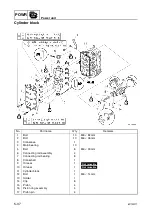
Power unit
5-27
6C13G11
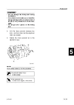
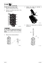
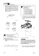
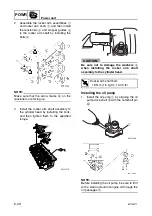
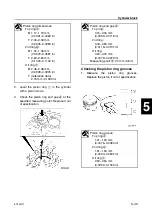
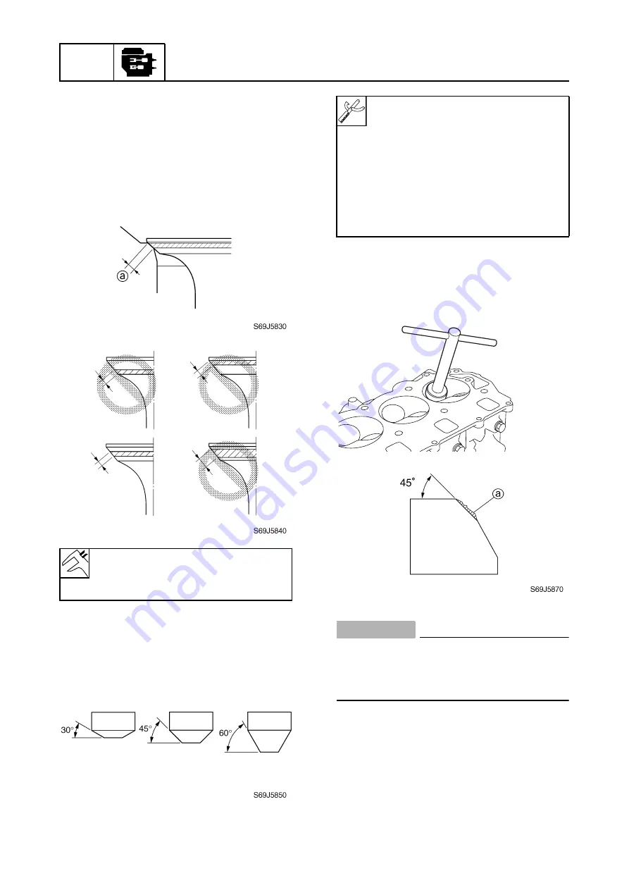
4.
Measure the valve seat contact width
a
where the blueing dye is adhered to the
valve face. Reface the valve seat if the
valve is not seated properly or if the valve
seat contact width is out of specification.
Replace the valve guide if the valve seat
contact is uneven.
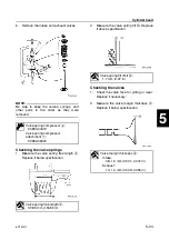
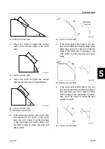
Refacing the valve seat
1.
Reface the valve seat with the valve seat
cutters.
2.
Cut the surface of the valve seat with a
45° cutter by turning the cutter clockwise
until the valve seat face has become
smooth.
a
Slag or rough surface
CAUTION:
Do not over cut the valve seat. Be sure to
turn the cutter evenly downward at a pres-
sure of 40–50 N (4–5 kgf, 8.8–11 lbf) to
prevent chatter marks.
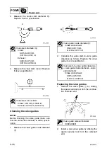
3.
Use a 30° cutter to adjust the contact
width of the top edge of the valve seat.
Valve seat contact width
a
:
Intake and exhaust:
1.3–1.5 mm (0.051–0.059 in)
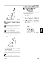
Valve seat cutter holder:
90890-06316
Valve seat cutter:
30° (intake): 90890-06327
30° (exhaust): 90890-06328
45° (intake): 90890-06555
45° (exhaust): 90890-06312
60° (intake): 90890-06323
60° (exhaust): 90890-06315
S6C15480
Summary of Contents for F50F
Page 1: ...F50F FT50G F60C FT60D SERVICE MANUAL 6C1 28197 3G 11 290551 ...
Page 4: ......
Page 48: ...SPEC Specifications 2 25 6C13G11 MEMO ...
Page 190: ...LOWR Lower unit 6 47 6C13G11 Shimming FT50 FT60 6 ...
Page 195: ...6C13G11 6 52 1 2 3 4 5 6 7 8 9 MEMO Backlash FT50 FT60 ...
Page 221: ...6C13G11 7 24 1 2 3 4 5 6 7 8 9 Steering arm ...
Page 249: ...6C13G11 7 52 1 2 3 4 5 6 7 8 9 MEMO Power trim and tilt electrical system ...
Page 272: ...ELEC Electrical systems 8 21 6C13G11 MEMO ...
Page 301: ...6C13G11 i 5 1 2 3 4 5 6 7 8 9 Index MEMO ...
Page 303: ......
Page 304: ...YAMAHA MOTOR CO LTD Printed in the Netherlands Jul 2004 1 2 1 CR E_2 ...