POWR
Power unit
5-49
6C13G11
14. Install the oil filter, and then tighten it to
the specified torque using the oil filter
wrench.
NOTE:
Apply a thin coat of engine oil to the O-ring of
the new oil filter before installation.
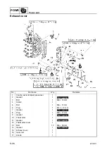
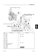
15. Install a new gasket and the exhaust
cover.
16. Install the thermostat and thermostat
cover, and then tighten the bolts to the
specified torques in two stages and in the
sequence shown.
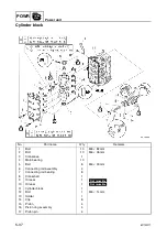
17. Install the cylinder head.
NOTE:
For installation procedure, see “Installing the
cylinder head.”
Installing the power unit
1.
Clean the power unit mating surface, and
install the dowels
1
and a new gasket
2
.
2.
Install the power unit
3
by installing the
bolts
4
, then tightening them to the
specified torque.
3.
Install the apron.
4.
Connect the flushing hose, cooling water
pilot hose, and fuel hose.
5.
Install the oil dipstick.
6.
Install the shift rod bolts
5
.
Oil filter wrench: 90890-01426
T
R
.
.
Oil filter:
18 N·m (1.8 kgf·m, 13.3 ft·lb)
T
R
.
.
Exhaust cover bolt:
1st: 6 N·m (0.6 kgf·m, 4.4 ft·lb)
2nd: 12 N·m (1.2 kgf·m, 8.9 ft·lb)
S6C15780
E
S6C15790
T
R
.
.
Power unit mounting bolt
4
:
27 N·m (2.7 kgf·m, 20.0 ft·lb)
S6C15810
5
Summary of Contents for F50F
Page 1: ...F50F FT50G F60C FT60D SERVICE MANUAL 6C1 28197 3G 11 290551 ...
Page 4: ......
Page 48: ...SPEC Specifications 2 25 6C13G11 MEMO ...
Page 190: ...LOWR Lower unit 6 47 6C13G11 Shimming FT50 FT60 6 ...
Page 195: ...6C13G11 6 52 1 2 3 4 5 6 7 8 9 MEMO Backlash FT50 FT60 ...
Page 221: ...6C13G11 7 24 1 2 3 4 5 6 7 8 9 Steering arm ...
Page 249: ...6C13G11 7 52 1 2 3 4 5 6 7 8 9 MEMO Power trim and tilt electrical system ...
Page 272: ...ELEC Electrical systems 8 21 6C13G11 MEMO ...
Page 301: ...6C13G11 i 5 1 2 3 4 5 6 7 8 9 Index MEMO ...
Page 303: ......
Page 304: ...YAMAHA MOTOR CO LTD Printed in the Netherlands Jul 2004 1 2 1 CR E_2 ...

