FUEL
Fuel system
4-11
6C13G11
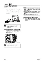
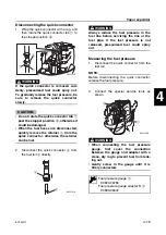
Checking the throttle position
sensor
1.
Check the throttle position sensor output
voltage using the Yamaha Diagnostic
System. If the output voltage is out of
specification, replace the throttle posi-
tion sensor.
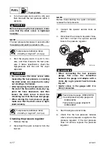
Installing the throttle position sensor
1.
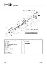
Install the throttle position sensor
1
in a
position where the output voltage is
within specification.
NOTE:
• If the throttle position sensor output voltage
is out of specification, reinstall the throttle
position sensor.
• Measure the throttle position sensor output
voltage using the Yamaha Diagnostic Sys-
tem.
• Do not turn the throttle stop screw
a
.
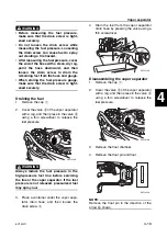
Checking the idle speed control
1.
Check the operation of the idle speed
control using the Yamaha Diagnostic
System.
Throttle position sensor output
voltage at engine idle speed:
0.8–1.2 V
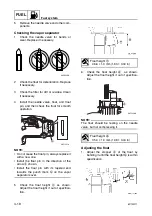
Throttle position sensor output
voltage at engine idle speed:
0.8–1.2 V
S6C14350
S6C14310
a
1
Summary of Contents for F50F
Page 1: ...F50F FT50G F60C FT60D SERVICE MANUAL 6C1 28197 3G 11 290551 ...
Page 4: ......
Page 48: ...SPEC Specifications 2 25 6C13G11 MEMO ...
Page 190: ...LOWR Lower unit 6 47 6C13G11 Shimming FT50 FT60 6 ...
Page 195: ...6C13G11 6 52 1 2 3 4 5 6 7 8 9 MEMO Backlash FT50 FT60 ...
Page 221: ...6C13G11 7 24 1 2 3 4 5 6 7 8 9 Steering arm ...
Page 249: ...6C13G11 7 52 1 2 3 4 5 6 7 8 9 MEMO Power trim and tilt electrical system ...
Page 272: ...ELEC Electrical systems 8 21 6C13G11 MEMO ...
Page 301: ...6C13G11 i 5 1 2 3 4 5 6 7 8 9 Index MEMO ...
Page 303: ......
Page 304: ...YAMAHA MOTOR CO LTD Printed in the Netherlands Jul 2004 1 2 1 CR E_2 ...


