


6C13G11
7-44
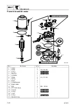
1
2
3
4
5
6
7
8
9
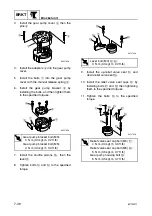
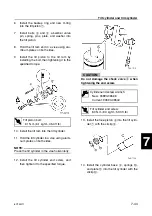
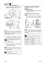
6.
Install the backup ring and new O-ring
into the tilt piston
7
.
7.
Install balls
8
and
9
, absorber valve
pin, spring, pins, plate, and washer into
the tilt piston.
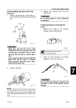
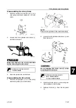
8.
Hold the tilt ram end in a vise using alu-
minum plates on both sides.
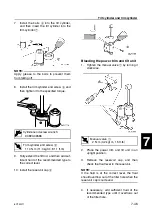
9.
Install the tilt piston to the tilt ram by
installing the bolt, then tightening it to the
specified torque.
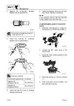
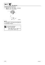
10. Install the tilt ram into the tilt cylinder.
11. Hold the tilt cylinder in a vise using alumi-
num plates on both sides.
NOTE:
Place the tilt cylinder in the vise horizontally.
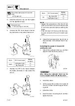
12. Install the tilt cylinder end screw, and
then tighten it to the specified torque.
CAUTION:
Do not damage the check valve
a
when
tightening the end screw.
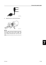
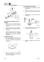
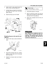
13. Install the free piston
6
into the tilt cylin-
der
7
with the circlip
8
.
14. Install the cylinder base
9
, springs
0
,
and plate
A
into the tilt cylinder with the
circlip
B
.
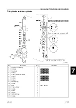
T
R
.
.
Tilt piston bolt:
61 N·m (6.1 kgf·m, 45.0 ft·lb)
Cylinder-end screw wrench:
New: 90890-06568
Current: 90890-06544
T
R
.
.
Tilt cylinder end screw:
80 N·m (8.0 kgf·m, 59.0 ft·lb)
Summary of Contents for F50F
Page 1: ...F50F FT50G F60C FT60D SERVICE MANUAL 6C1 28197 3G 11 290551 ...
Page 4: ......
Page 48: ...SPEC Specifications 2 25 6C13G11 MEMO ...
Page 190: ...LOWR Lower unit 6 47 6C13G11 Shimming FT50 FT60 6 ...
Page 195: ...6C13G11 6 52 1 2 3 4 5 6 7 8 9 MEMO Backlash FT50 FT60 ...
Page 221: ...6C13G11 7 24 1 2 3 4 5 6 7 8 9 Steering arm ...
Page 249: ...6C13G11 7 52 1 2 3 4 5 6 7 8 9 MEMO Power trim and tilt electrical system ...
Page 272: ...ELEC Electrical systems 8 21 6C13G11 MEMO ...
Page 301: ...6C13G11 i 5 1 2 3 4 5 6 7 8 9 Index MEMO ...
Page 303: ......
Page 304: ...YAMAHA MOTOR CO LTD Printed in the Netherlands Jul 2004 1 2 1 CR E_2 ...