FUEL
Fuel system
4-17
6C13G11
3.
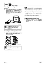
Turn the engine start switch to ON, and
then measure the fuel pressure within 3
seconds.
WARNING
Before measuring the fuel pressure, make
sure that the drain screw is tightened
securely.
NOTE:
The fuel pressure decreases 3 seconds after
the engine start switch is turned to ON.
4.
Start the engine, warm it up for 5 min-
utes, and then measure the fuel pres-
sure. If below specification, check the
high-pressure fuel line and the vapor
separator.
WARNING
• Do not loosen the drain screw while
measuring the fuel pressure. Loosening
the drain screw can cause fuel to spray
out creating a fire hazard.
• After measuring the fuel pressure, cover
the end of the hose with a clean, dry rag,
point the hose downward, and then
loosen the drain screw to drain the
remaining fuel from the hose and gauge.
• When storing the fuel pressure gauge,
make sure that the drain screw is tight-
ened securely.
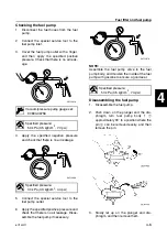
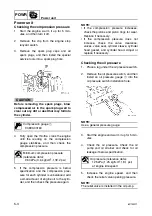
Checking the pressure regulator
1.
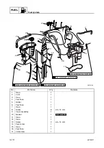
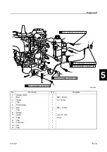
Remove the cap.
2.
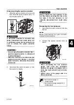
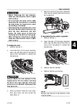
Disconnect the quick connector from the
fuel rail.
NOTE:
Before disconnecting the quick connector,
release the fuel pressure.
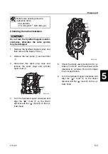
3.
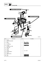
Connect the special service tools as
shown.
4.
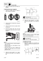
Disconnect the pressure regulator hose,
and then connect the special service
tools to the pressure regulator.
WARNING
• When connecting the fuel pressure
gauge, first cover the connection
between the gauge and adapter with a
clean, dry rag to prevent fuel from leak-
ing out.
• Gently screw in the gauge until it is
firmly connected.
5.
Start the engine and let it idle.
6.
Check that the fuel pressure reduces
when vacuum pressure is applied to the
pressure regulator. If the fuel pressure
does not reduce, replace the pressure
regulator.
Fuel pressure (reference data):
290 kPa (2.9 kgf/cm
2
, 41.2 psi)
Fuel pressure (reference data):
230 kPa (2.3 kgf/cm
2
, 32.7 psi)
Fuel pressure gauge: 90890-06786
Vacuum/pressure pump gauge set:
90890-06756
Fuel pressure gauge adapter B:
90890-06942
S6C14160
Summary of Contents for F50F
Page 1: ...F50F FT50G F60C FT60D SERVICE MANUAL 6C1 28197 3G 11 290551 ...
Page 4: ......
Page 48: ...SPEC Specifications 2 25 6C13G11 MEMO ...
Page 190: ...LOWR Lower unit 6 47 6C13G11 Shimming FT50 FT60 6 ...
Page 195: ...6C13G11 6 52 1 2 3 4 5 6 7 8 9 MEMO Backlash FT50 FT60 ...
Page 221: ...6C13G11 7 24 1 2 3 4 5 6 7 8 9 Steering arm ...
Page 249: ...6C13G11 7 52 1 2 3 4 5 6 7 8 9 MEMO Power trim and tilt electrical system ...
Page 272: ...ELEC Electrical systems 8 21 6C13G11 MEMO ...
Page 301: ...6C13G11 i 5 1 2 3 4 5 6 7 8 9 Index MEMO ...
Page 303: ......
Page 304: ...YAMAHA MOTOR CO LTD Printed in the Netherlands Jul 2004 1 2 1 CR E_2 ...

