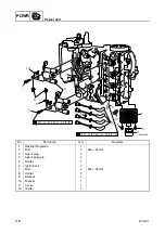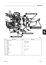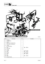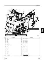
6C13G11
5-4
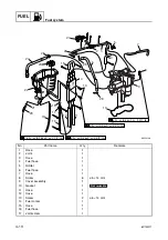
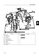
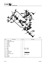
1
2
3
4
5
6
7
8
9
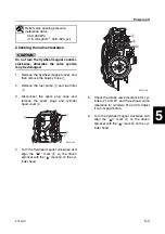
Checking the valve clearance
CAUTION:
Do not turn the flywheel magnet counter-
clockwise, otherwise the valve system
may be damaged.
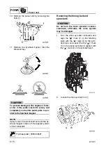
1.
Remove the flywheel magnet cover, and
then remove the blowby hose
1
.
2.
Remove the fuel pump
2
and fuel filter
3
.
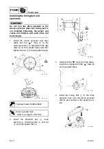
3.
Disconnect the spark plug caps and
remove the spark plugs and cylinder
head cover
4
.
4.
Turn the flywheel magnet clockwise and
align the “
1” mark
a
on the driven
sprocket with the “
” mark
b
on the cyl-
inder head.
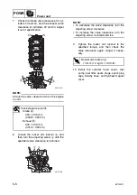
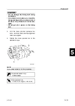
5.
Check the intake valve clearance for cyl-
inders #1 and #2, and the exhaust valve
clearance for cylinders #1 and #3. Adjust
if out of specification.
6.
Turn the flywheel magnet clockwise and
align the “
4” mark
c
on the driven
sprocket with the “
” mark
b
on the cyl-
inder head.
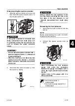
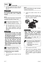
Relief valve opening pressure
(reference data):
350–450 kPa
(3.5–4.5 kgf/cm
2
, 50.8–62.3 psi)
S6C15130
1
3
4
2
S6C15140
c
b
a
Summary of Contents for F50F
Page 1: ...F50F FT50G F60C FT60D SERVICE MANUAL 6C1 28197 3G 11 290551 ...
Page 4: ......
Page 48: ...SPEC Specifications 2 25 6C13G11 MEMO ...
Page 190: ...LOWR Lower unit 6 47 6C13G11 Shimming FT50 FT60 6 ...
Page 195: ...6C13G11 6 52 1 2 3 4 5 6 7 8 9 MEMO Backlash FT50 FT60 ...
Page 221: ...6C13G11 7 24 1 2 3 4 5 6 7 8 9 Steering arm ...
Page 249: ...6C13G11 7 52 1 2 3 4 5 6 7 8 9 MEMO Power trim and tilt electrical system ...
Page 272: ...ELEC Electrical systems 8 21 6C13G11 MEMO ...
Page 301: ...6C13G11 i 5 1 2 3 4 5 6 7 8 9 Index MEMO ...
Page 303: ......
Page 304: ...YAMAHA MOTOR CO LTD Printed in the Netherlands Jul 2004 1 2 1 CR E_2 ...


