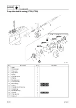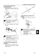
6C13G11
6-20
1
2
3
4
5
6
7
8
9
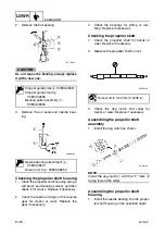
2.
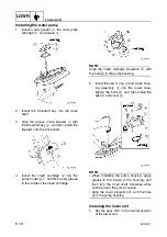
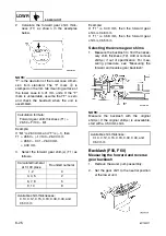
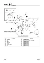
Align the center of the set pin
a
with the
alignment mark
b
on the bracket.
3.
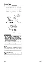
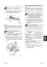
Install the two dowels
1
into the lower
unit.
4.
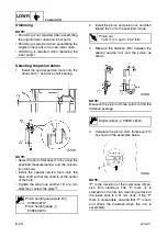
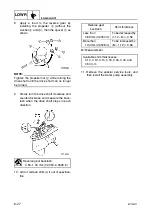
Install the lower unit into the upper case,
and then tighten the lower case mounting
bolts
2
to the specified torque.
5.
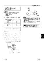
Install the trim tab
3
to its original posi-
tion, and then tighten the trim tab bolt
4
.
Shift rod push arm: 90890-06052
S6C16310
b
a
T
R
.
.
Lower case mounting bolt
2
:
39 N·m (3.9 kgf·m, 28.8 ft·lb)
Summary of Contents for F50F
Page 1: ...F50F FT50G F60C FT60D SERVICE MANUAL 6C1 28197 3G 11 290551 ...
Page 4: ......
Page 48: ...SPEC Specifications 2 25 6C13G11 MEMO ...
Page 190: ...LOWR Lower unit 6 47 6C13G11 Shimming FT50 FT60 6 ...
Page 195: ...6C13G11 6 52 1 2 3 4 5 6 7 8 9 MEMO Backlash FT50 FT60 ...
Page 221: ...6C13G11 7 24 1 2 3 4 5 6 7 8 9 Steering arm ...
Page 249: ...6C13G11 7 52 1 2 3 4 5 6 7 8 9 MEMO Power trim and tilt electrical system ...
Page 272: ...ELEC Electrical systems 8 21 6C13G11 MEMO ...
Page 301: ...6C13G11 i 5 1 2 3 4 5 6 7 8 9 Index MEMO ...
Page 303: ......
Page 304: ...YAMAHA MOTOR CO LTD Printed in the Netherlands Jul 2004 1 2 1 CR E_2 ...


