


POWR
Power unit
5-45
6C13G11
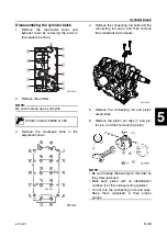
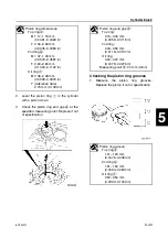
6.
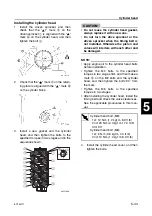
Install the crankcase onto the cylinder
block.
7.
Apply engine oil to the threads of the
crankcase bolts, and then tighten them to
the specified torques in two stages and in
the sequence shown.
8.
Remove the crankcase, and then mea-
sure the width of the compressed Plasti-
gauge (PG-1) on each main journal.
Replace the main bearing if out of speci-
fication.
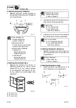
Selecting the main bearings
1.
When replacing the main bearing, select
the suitable bearing as follows.
2.
Check the crankshaft journal mark on the
crankshaft
1
and the cylinder block mark
on the cylinder block
2
.
3.
Select the suitable color
a
for the main
bearing from the table.
T
R
.
.
Crankcase bolt (M8):
1st: 15 N·m (1.5 kgf·m, 11.1 ft·lb)
2nd: 30 N·m (3.0 kgf·m, 22.1 ft·lb)
Crankcase bolt (M6):
1st: 6 N·m (0.6 kgf·m, 4.4 ft·lb)
2nd: 12 N·m (1.2 kgf·m, 8.9 ft·lb)
Crankshaft main journal oil
clearance:
0.012–0.036 mm
(0.0005–0.0014 in)
Summary of Contents for F50F
Page 1: ...F50F FT50G F60C FT60D SERVICE MANUAL 6C1 28197 3G 11 290551 ...
Page 4: ......
Page 48: ...SPEC Specifications 2 25 6C13G11 MEMO ...
Page 190: ...LOWR Lower unit 6 47 6C13G11 Shimming FT50 FT60 6 ...
Page 195: ...6C13G11 6 52 1 2 3 4 5 6 7 8 9 MEMO Backlash FT50 FT60 ...
Page 221: ...6C13G11 7 24 1 2 3 4 5 6 7 8 9 Steering arm ...
Page 249: ...6C13G11 7 52 1 2 3 4 5 6 7 8 9 MEMO Power trim and tilt electrical system ...
Page 272: ...ELEC Electrical systems 8 21 6C13G11 MEMO ...
Page 301: ...6C13G11 i 5 1 2 3 4 5 6 7 8 9 Index MEMO ...
Page 303: ......
Page 304: ...YAMAHA MOTOR CO LTD Printed in the Netherlands Jul 2004 1 2 1 CR E_2 ...