6C13G11
3-10
1
2
3
4
5
6
7
8
9
5.
Install the thermostat, gasket, and cover.
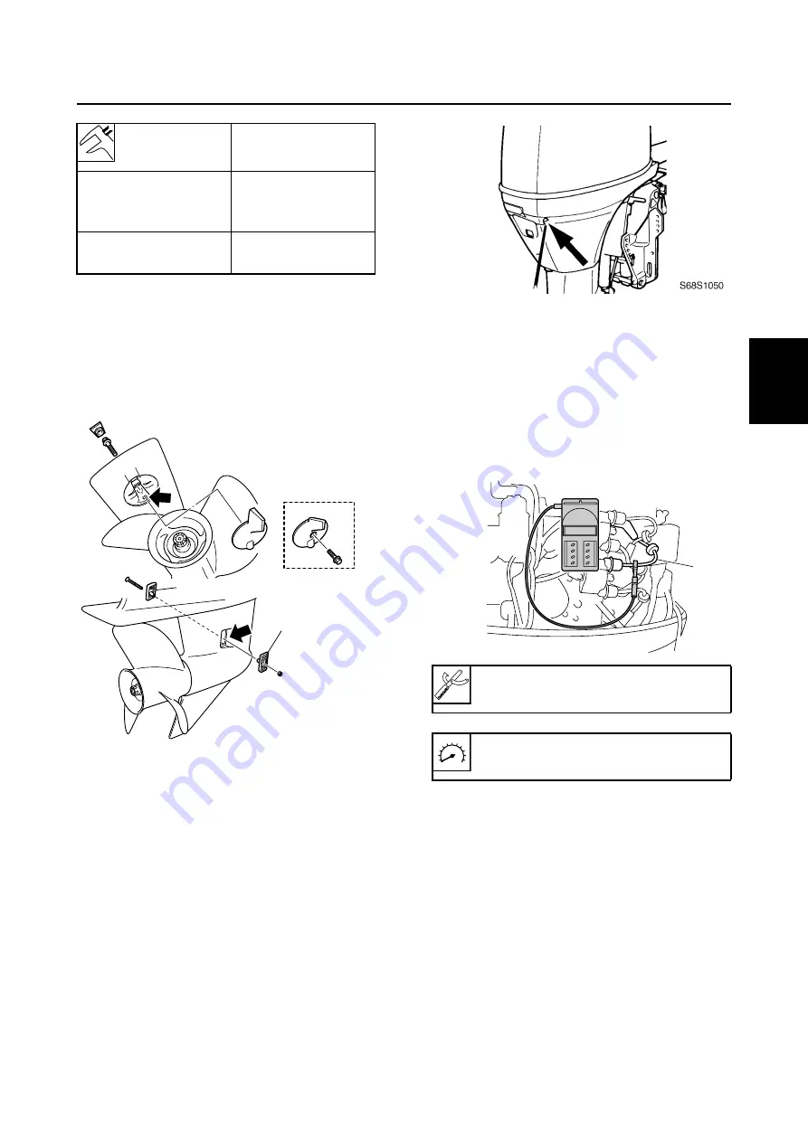
Checking the cooling water passage
1.
Check the cooling water inlet cover
1
and cooling water inlet for clogs. Clean if
necessary.
È
F50, F60
2.
Place the lower unit in water, and then
start the engine.
3.
Check for water flow at the cooling water
pilot hole. If there is no water flow, check
the cooling water passage inside the out-
board motor.
Control system
3
Checking the engine idle speed
1.
Start the engine and warm it up for 5 min-
utes.
2.
Attach the special service tool to spark
plug wire #1
1
, and then check the
engine idle speed.
Adjusting the throttle link and
throttle cable
1.
Set the remote control lever to the neu-
tral position and fully close the throttle
lever. Set the throttle grip to the fully
closed position.
2.
Disconnect the throttle link rod from the
throttle body and the throttle link.
Water
temperature
Valve lift
a
58–62 °C
(136–144 °F)
0.05 mm
(0.0020 in)
(valve begins to lift)
above
70 °C (158 °F)
more than
3.0 mm (0.12 in)
S6C13100
1
1
È
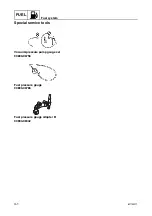
Digital tachometer: 90890-06760
Engine idle speed: 700–800 r/min
S6C13110
1
Summary of Contents for F50F
Page 1: ...F50F FT50G F60C FT60D SERVICE MANUAL 6C1 28197 3G 11 290551 ...
Page 4: ......
Page 48: ...SPEC Specifications 2 25 6C13G11 MEMO ...
Page 190: ...LOWR Lower unit 6 47 6C13G11 Shimming FT50 FT60 6 ...
Page 195: ...6C13G11 6 52 1 2 3 4 5 6 7 8 9 MEMO Backlash FT50 FT60 ...
Page 221: ...6C13G11 7 24 1 2 3 4 5 6 7 8 9 Steering arm ...
Page 249: ...6C13G11 7 52 1 2 3 4 5 6 7 8 9 MEMO Power trim and tilt electrical system ...
Page 272: ...ELEC Electrical systems 8 21 6C13G11 MEMO ...
Page 301: ...6C13G11 i 5 1 2 3 4 5 6 7 8 9 Index MEMO ...
Page 303: ......
Page 304: ...YAMAHA MOTOR CO LTD Printed in the Netherlands Jul 2004 1 2 1 CR E_2 ...


