6C13G11
8-8
1
2
3
4
5
6
7
8
9
Ignition and ignition control
system
8
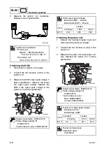
Checking the ignition spark
1.
Disconnect the spark plug caps from the
spark plugs.
2.
Connect a spark plug cap to the special
service tool.
3.
Crank the engine and observe the spark
through the discharge window of the spe-
cial service tool. Check the ignition sys-
tem if the spark is weak.
WARNING
• Do not touch any of the connections of
the ignition tester leads.
• Do not let sparks leak out of the
removed spark plug caps.
• Keep flammable gas or liquids away,
since this test can produce sparks.
NOTE:
The ignition spark can also be checked using
the “Stationary test” of the Yamaha Diagnos-
tic System.
Checking the spark plug wires
1.
Remove the spark plug wires from the
spark plugs.
2.
Remove the spark plug wires from the
ignition coils.
3.
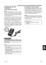
Measure the spark plug wire resistance.
Replace if out of specification.
Checking the ignition coils
1.
Remove the spark plug wires from the
ignition coils.
2.
Disconnect the ignition coil coupler.
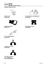
Ignition tester: 90890-06754
Spark plug wire resistance:
1.9–5.0 k
Ω
S6C18210
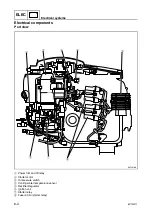
Electrical components / Ignition and ignition control system
Summary of Contents for F50F
Page 1: ...F50F FT50G F60C FT60D SERVICE MANUAL 6C1 28197 3G 11 290551 ...
Page 4: ......
Page 48: ...SPEC Specifications 2 25 6C13G11 MEMO ...
Page 190: ...LOWR Lower unit 6 47 6C13G11 Shimming FT50 FT60 6 ...
Page 195: ...6C13G11 6 52 1 2 3 4 5 6 7 8 9 MEMO Backlash FT50 FT60 ...
Page 221: ...6C13G11 7 24 1 2 3 4 5 6 7 8 9 Steering arm ...
Page 249: ...6C13G11 7 52 1 2 3 4 5 6 7 8 9 MEMO Power trim and tilt electrical system ...
Page 272: ...ELEC Electrical systems 8 21 6C13G11 MEMO ...
Page 301: ...6C13G11 i 5 1 2 3 4 5 6 7 8 9 Index MEMO ...
Page 303: ......
Page 304: ...YAMAHA MOTOR CO LTD Printed in the Netherlands Jul 2004 1 2 1 CR E_2 ...

