Page
152
of
244
4.6.4.
Center Ball Size Calibration
1. Acquire the PANO Ball Phantom image and open it.
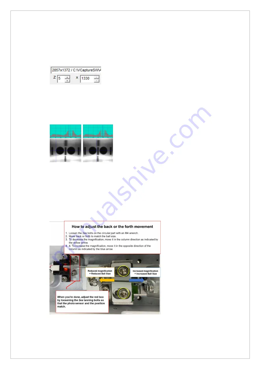
2. Enter 5 in the Z box, and drag the mouse to see the Center Balls
3. Click the starting point of the Right Center Ball and read the X value by pixel.
4. Click the end point of the Right Center Ball and read the X value by pixel.
5. Subtract the starting point value from the end point value to measure the Right Center Ball
size.
6. Check the Right Center Ball size meets the standard(54 ~ 55 pixels).
7. Do steps 3 ~ 6 for the Left Center Ball.
8. If it is out of the standard value, move the position of the PANO Mode Chinrest Fixed Block
and adjust the ball size.
9. When Ball Size is 56 Pixels or more: Move the Chinrest in the direction of Column.
10. If the ball size is less than 53 Pixel: Move the Chinrest in the opposite direction of Column.
When all of the above operations are completed, adjust by loosening 2 headless bolts on the red
square display so that there is no interference between the photo sensor and the blade
Summary of Contents for A9 PHT-30CSS
Page 1: ...vatech A9 Technical manual Model PHT 30CSS Version 1 01 English...
Page 12: ...Page 11 of 244 1 2 1 Vertical Frame Part...
Page 22: ...Page 21 of 244 1 2 3 5 Generator DG 07E22T2...
Page 26: ...Page 25 of 244...
Page 27: ...Page 26 of 244...
Page 30: ...Page 29 of 244 1 3 3 Sensor Part Connection Diagram...
Page 31: ...Page 30 of 244 1 3 4 CEPH SENSOR Part Connection Diagram...
Page 32: ...Page 31 of 244 1 3 5 Connection Diagram Total assembly...
Page 43: ...Page 42 of 244 16 Loosen ten bolts as shown in the image below...
Page 112: ...Page 111 of 244 5 Click the V Vol button Click the Ready button...
Page 180: ...Page 179 of 244 10 Select 50 in the M box and click the center of the flat washer...
Page 209: ...Page 208 of 244 8 5 Appendix 8 5 1 Main MCU Board Parameters...
Page 244: ...vatech A9 www vatech com...


