


6-8
System Setup and Diagnostics
Setting Servo Gains
Trio Motion Technology
Setting Servo Gains
The servo system controls the motor by constantly adjusting the voltage out-
put which gives a speed demand to the servo drive. The speed demand is
worked out by looking at the measured position of the axis from the encoder
comparing it with the demand position generated by the Motion Coordinator.
The demand position is constantly being changed by the Motion Coordinator
during a move. The difference between the demand position (Where you want
the motor to be) and the measured position (Where it actually is) is called the
following error.
The controller checks the following error typically 1000 times per second and
updates the voltage output according to the “servo function”. The Motion
Coordinator has 5 gain values which control how the servo function generates
the voltage output from the following error.
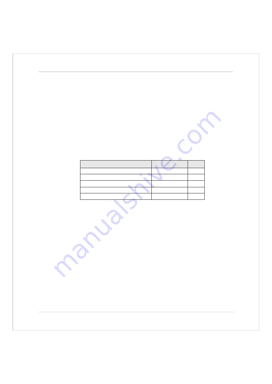
Default Settings:
A simple test program can be used to generate movement to and fro for exam-
ination of the motion profile generated on an oscilloscope. The oscilloscope
should be connected to the tacho or velocity output from the servo drive.
Example:
PRINT "Enter Axis Number ":INPUT VR(0)
BASE(VR(0))
SPEED=20000
ACCEL=200000
DECEL=200000
loop:
MOVE(1000)
WAIT IDLE
WA(100)
MOVE(-1000)
WAIT IDLE
WA(100)
GOTO loop
Gain
Parameter Name
Value
Proportional Gain
P_GAIN
1.0
Integral Gain
I_GAIN
0.0
Derivative Gain
D_GAIN
0.0
Output Velocity Gain
OV_GAIN
0.0
Velocity Feedforward Gain
VFF_GAIN
0.0
Summary of Contents for Motion Coordinator Euro 205
Page 4: ......
Page 11: ...C H A P T E R CHAPTER0INTRODUCTION...
Page 12: ......
Page 27: ...C H A P T E R CHAPTER0HARDWARE OVERVIEW...
Page 28: ......
Page 35: ...Motion Coordinator Technical Reference Manual Hardware Overview 2 9 Motion Coordinator MC202...
Page 75: ...C H A P T E R CHAPTER0INSTALLATION...
Page 76: ......
Page 88: ...3 14 Installation EMC Considerations Trio Motion Technology...
Page 89: ...C H A P T E R CHAPTER0DAUGHTER BOARDS...
Page 90: ......
Page 126: ...4 38 Daughter Boards Profibus Daughter Board Trio Motion Technology...
Page 127: ...C H A P T E R CHAPTER0EXPANSION MODULES...
Page 128: ......
Page 158: ...5 32 Expansion Modules Communications Adaptors Trio Motion Technology...
Page 159: ...C H A P T E R CHAPTER0SYSTEM SETUP AND DIAGNOSTICS...
Page 160: ......
Page 173: ...C H A P T E R CHAPTER 0PROGRAMMING...
Page 174: ...7 2 Programming Trio Motion Technology...
Page 190: ...7 18 Programming Command Line Interface Trio Motion Technology...
Page 191: ...C H A P T E R CHAPTER0TRIO BASIC COMMANDS...
Page 192: ......
Page 200: ...8 10 Trio BASIC Commands Trio Motion Technology VERIFY 8 178 VFF_GAIN 8 178 VP_SPEED 8 179...
Page 254: ...8 64 Trio BASIC Commands Input Output Commands Trio Motion Technology...
Page 372: ...8 182Trio BASIC Commands Axis Parameters Trio Motion Technology...
Page 373: ...C H A P T E R CHAPTER 0PROGRAMMING EXAMPLES...
Page 374: ......
Page 389: ...C H A P T E R CHAPTER0SUPPORT SOFTWARE...
Page 390: ......
Page 472: ...10 84Support Software Project Autoloader Trio Motion Technology...
Page 473: ...C H A P T E R CHAPTER0FIBRE OPTIC NETWORK...
Page 474: ......
Page 486: ...11 14Fibre Optic Network Network Specification Trio Motion Technology...
Page 487: ...C H A P T E R CHAPTER0USING THE TRIO ACTIVEX CONTROL...
Page 488: ......
Page 518: ...12 32Using the Trio ActiveX Control Events Trio Motion Technology...
Page 519: ...C H A P T E R CHAPTER0COMMUNICATIONS PROTOCOLS...
Page 520: ......
Page 551: ...A P P E N D I X CHAPTER 0REFERENCE...
Page 552: ......


