INSPECTION AND ADJUSTMENT OF
VALVE CLEARANCE
HINT: Adjust the valve clearance while the engine is cold.
1.
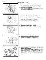
REMOVE AIR INTAKE CHAMBER
(See steps 1 to 14 pages
and 29)
2.
REMOVE CYLINDER HEAD COVERS
(See step 32 on page
)
3.
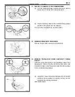
SET NO.1 CYLINDER TO TDC/COMPRESSION
(a) Turn the crankshaft pulley, and align its groove with the
timing mark “0” of the No.1 timing belt cover.
(b) Check that the valve lifters on the No.1 (IN) are loose
and valve lifters on the No.1 (EX) are tight.
If not, turn the crankshaft one revolution (360
°
) and align the
mark as above.
4. ADJUST
VALVE
CLEARANCE
(a) Check only those valves indicated in the figure.
•
Using a feeler gauge, measure the clearance
between the valve lifter and camshaft.
•
Record out of specification valve clearance
measurements. They will be used later to determine
the required replacement adjusting shim.
Valve clearance (Cold):
Intake 0.13–0.23 mm (0.005–0.009 in.)
Exhaust 0.27–0.37 mm (0.011–0.015 in.)
(b) Turn the crankshaft 2/3 of a revolution (240
°
), and check
only the valves indicated in the figure.
Measure the valve clearance.
(See procedure step (a))
(c) Turn the crankshaft further 2/3 of a revolution (240
°
),
and check only the valves indicated in the figure.
Measure the valve clearance.
(See procedure step (a))
EM-8
ENGINE MECHANICAL – Engine Tune–Up
Summary of Contents for 2VZ-FE
Page 1: ...ENGINE MECHANICAL EM 1 ENGINE MECHANICAL Description Operation ...
Page 31: ...CYLINDER HEADS COMPONENTS EM 29 ENGINE MECHANICAL Cylinder Heads ...
Page 63: ...CYLINDER BLOCK REMOVAL OF ENGINE EM 61 ENGINE MECHANICAL Cylinder Block ...
Page 64: ...EM 62 ENGINE MECHANICAL Cylinder Block ...
Page 71: ...COMPONENTS EM 69 ENGINE MECHANICAL Cylinder Block ...
Page 106: ...EFI SYSTEM FI 1 ...
Page 107: ...DESCRIPTION FI 2 EFI SYSTEM Description ...
Page 111: ...OPERATION System Circuit FI 4 EFI SYSTEM Operation System Circuit ...
Page 121: ...FUEL SYSTEM Fuel Pump EFI SYSTEM Fuel System Fuel Pump FI 15 ...
Page 141: ...Fuel Tank and Lines COMPONENTS EFI SYSTEM Fuel System Fuel Tank and Lines FI 35 ...
Page 172: ...EXHAUST SYSTEM EXHAUST SYSTEM REPAIR INSTRUCTIONS EX 1 ...
Page 174: ...EMISSION CONTROL SYSTEMS EC 1 ...
Page 186: ...COOLING SYSTEM CO 1 ...
Page 205: ...LUBRICATION SYSTEM LUBRICATION SYSTEM Description Operation LU 1 ...
Page 224: ...IGNITION SYSTEM IG 1 ...
Page 237: ...SERVICE SPECIFICATIONS IG 14 IGNITION SYSTEM ServiceSpecifications ...
Page 238: ...ENGINE TROUBLESHOOTING TR 1 ...


