9.
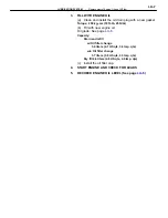
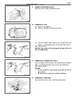
REMOVE STIFFENER PLATE
Remove the two bolts and stiffener plate.
10. REMOVE OIL PAN
(a) Remove
the
dipstick.
(b) Remove the fifteen bolts and four nuts.
(c) Insert the blade of SST between the cylinder block and
oil pan, cut off applied sealer and remove the oil pan.
SST 09032–00100
NOTICE: Be careful not to damage the flanges of the oil
pan and baffle plate.
11. REMOVE OIL PAN BAFFLE PLATE
Insert the blade of SST between the cylinder block and baffle
plate, cut off applied sealer and remove the baffle plate.
SST 09032–00100
NOTICE:
•
Do not use SST for the oil pump body side and rear oil
seal retainer.
•
Be careful not to damage the baffle plate flange.
12. REMOVE OIL STRAINER
Remove the bolt, two nuts, oil strainer and gasket.
–
LUBRICATION SYSTEM
Oil Pump
LU–9
Summary of Contents for 2VZ-FE
Page 1: ...ENGINE MECHANICAL EM 1 ENGINE MECHANICAL Description Operation ...
Page 31: ...CYLINDER HEADS COMPONENTS EM 29 ENGINE MECHANICAL Cylinder Heads ...
Page 63: ...CYLINDER BLOCK REMOVAL OF ENGINE EM 61 ENGINE MECHANICAL Cylinder Block ...
Page 64: ...EM 62 ENGINE MECHANICAL Cylinder Block ...
Page 71: ...COMPONENTS EM 69 ENGINE MECHANICAL Cylinder Block ...
Page 106: ...EFI SYSTEM FI 1 ...
Page 107: ...DESCRIPTION FI 2 EFI SYSTEM Description ...
Page 111: ...OPERATION System Circuit FI 4 EFI SYSTEM Operation System Circuit ...
Page 121: ...FUEL SYSTEM Fuel Pump EFI SYSTEM Fuel System Fuel Pump FI 15 ...
Page 141: ...Fuel Tank and Lines COMPONENTS EFI SYSTEM Fuel System Fuel Tank and Lines FI 35 ...
Page 172: ...EXHAUST SYSTEM EXHAUST SYSTEM REPAIR INSTRUCTIONS EX 1 ...
Page 174: ...EMISSION CONTROL SYSTEMS EC 1 ...
Page 186: ...COOLING SYSTEM CO 1 ...
Page 205: ...LUBRICATION SYSTEM LUBRICATION SYSTEM Description Operation LU 1 ...
Page 224: ...IGNITION SYSTEM IG 1 ...
Page 237: ...SERVICE SPECIFICATIONS IG 14 IGNITION SYSTEM ServiceSpecifications ...
Page 238: ...ENGINE TROUBLESHOOTING TR 1 ...


