AIR INDUCTION SYSTEM
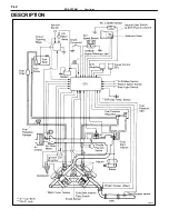
Air filtered through the air cleaner passes through the air flow meter and the amount flowing to the air intake
chamber is determined according to the throttle valve opening in the throttle body and the engine rpm.
The air flow meter measures the intake air flow by the opening of the measuring plate in response to the volume
of intake air to the engine.
Located in the throttle body is the throttle valve, which regulates the volume of intake air to the engine. Intake
air controlled by the throttle valve opening is distributed from the air intake chamber to the manifold of each cylin-
der and is drawn into the combustion chamber.
At low temperature the ISC valve opens, the air flows through the ISC valve, as well as the throttle body, into
the air intake chamber. During engine warming up, even if the throttle valve is completely closed, air flows to
the air intake chamber, thereby increasing the idle speed (first idle operation).
The air intake chamber prevents pulsation of the intake air, reduces the influence on the air flow meter and
increases the accuracy of the measurement of the intake air volume. It also prevents intake air interference in
each cylinder.
FI–6
–
EFI SYSTEM
Operation (System Operation)
Summary of Contents for 2VZ-FE
Page 1: ...ENGINE MECHANICAL EM 1 ENGINE MECHANICAL Description Operation ...
Page 31: ...CYLINDER HEADS COMPONENTS EM 29 ENGINE MECHANICAL Cylinder Heads ...
Page 63: ...CYLINDER BLOCK REMOVAL OF ENGINE EM 61 ENGINE MECHANICAL Cylinder Block ...
Page 64: ...EM 62 ENGINE MECHANICAL Cylinder Block ...
Page 71: ...COMPONENTS EM 69 ENGINE MECHANICAL Cylinder Block ...
Page 106: ...EFI SYSTEM FI 1 ...
Page 107: ...DESCRIPTION FI 2 EFI SYSTEM Description ...
Page 111: ...OPERATION System Circuit FI 4 EFI SYSTEM Operation System Circuit ...
Page 121: ...FUEL SYSTEM Fuel Pump EFI SYSTEM Fuel System Fuel Pump FI 15 ...
Page 141: ...Fuel Tank and Lines COMPONENTS EFI SYSTEM Fuel System Fuel Tank and Lines FI 35 ...
Page 172: ...EXHAUST SYSTEM EXHAUST SYSTEM REPAIR INSTRUCTIONS EX 1 ...
Page 174: ...EMISSION CONTROL SYSTEMS EC 1 ...
Page 186: ...COOLING SYSTEM CO 1 ...
Page 205: ...LUBRICATION SYSTEM LUBRICATION SYSTEM Description Operation LU 1 ...
Page 224: ...IGNITION SYSTEM IG 1 ...
Page 237: ...SERVICE SPECIFICATIONS IG 14 IGNITION SYSTEM ServiceSpecifications ...
Page 238: ...ENGINE TROUBLESHOOTING TR 1 ...

