Diag. Code
13
RPM Signal
CIRCUIT DESCRIPTION
The distributor in the Engine Control System contains three pick–up coils (G1, G2 and Ne).
The G1, G2 signals inform the ECU of the standard crankshaft angle.
The Ne signals inform the ECU of the crankshaft angle and the engine speed.
Code No.
Diagnosis
Trouble Area
13
NE signal not input to ECU for 50 msec. or
more when engine speed is 1,000 rpm or
more.
·
Open or short in NE circuit
·
Distributor
·
ECU
DIAGNOSTIC CHART
This code indicates that a momentary interruption of the RPM signal from the distributor to the ECU
has occurred, but that it is returned to normal. Note that although this problem may not necessarily
appear at the time of inspection, it cannot be ignored because this diagnostic code is output, indicating
that there is or was a malfunction in the RPM signal circuit; this “malfunction” is usually a loose
connector.
The distributor connector and the Ne terminal of the ECU connector must therefore be checked for
the following:
1. Loose
connectors
2.
Dirty connector terminals
3.
Loose connector terminals
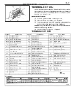
WIRING DIAGRAM AND ECU CONNECTORS
TR–28
–
ENGINE TROUBLESHOOTING
Circuit Inspection
Summary of Contents for 2VZ-FE
Page 1: ...ENGINE MECHANICAL EM 1 ENGINE MECHANICAL Description Operation ...
Page 31: ...CYLINDER HEADS COMPONENTS EM 29 ENGINE MECHANICAL Cylinder Heads ...
Page 63: ...CYLINDER BLOCK REMOVAL OF ENGINE EM 61 ENGINE MECHANICAL Cylinder Block ...
Page 64: ...EM 62 ENGINE MECHANICAL Cylinder Block ...
Page 71: ...COMPONENTS EM 69 ENGINE MECHANICAL Cylinder Block ...
Page 106: ...EFI SYSTEM FI 1 ...
Page 107: ...DESCRIPTION FI 2 EFI SYSTEM Description ...
Page 111: ...OPERATION System Circuit FI 4 EFI SYSTEM Operation System Circuit ...
Page 121: ...FUEL SYSTEM Fuel Pump EFI SYSTEM Fuel System Fuel Pump FI 15 ...
Page 141: ...Fuel Tank and Lines COMPONENTS EFI SYSTEM Fuel System Fuel Tank and Lines FI 35 ...
Page 172: ...EXHAUST SYSTEM EXHAUST SYSTEM REPAIR INSTRUCTIONS EX 1 ...
Page 174: ...EMISSION CONTROL SYSTEMS EC 1 ...
Page 186: ...COOLING SYSTEM CO 1 ...
Page 205: ...LUBRICATION SYSTEM LUBRICATION SYSTEM Description Operation LU 1 ...
Page 224: ...IGNITION SYSTEM IG 1 ...
Page 237: ...SERVICE SPECIFICATIONS IG 14 IGNITION SYSTEM ServiceSpecifications ...
Page 238: ...ENGINE TROUBLESHOOTING TR 1 ...

