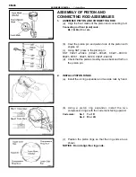
(i)
Remove the eight bolts and main bearing cap.
(See procedure (a) and (b) above)
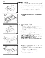
(j)
Measure the Plastigage at its widest point.
Standard clearance:
STD
0.029–0.056 mm
(0.0011–0.0022 in.)
U/S
0.25 0.028–0.080 mm
(0.0011–0.0031 in.)
Maximum clearance: 0.08 mm (0.0031 in.)
HINT: If replacing the cylinder block subassembly, the bear-
ing standard clearance will be:
0.031–0.067 mm (0.0012–0.0026 in.)
If the oil clearance is greater than maximum, replace the
bearings. If necessary, grind or replace the crankshaft.
HINT: If using a standard bearing, replace with one having
the same number. If the number of the bearing cannot be de-
termined, select the correct bearing by adding together the
numbers imprinted on the cylinder block and crankshaft, then
selecting the bearing with the same number as the total.
There are five sizes of standard bearings, marked “1”, “2”, “3”,
“4” and “5” accordingly.
Number marked
Cylinder block
1
2
3
Crankshaft
0
1
2
0
1
2
0
1
2
Bearing
1
2
3
2
3
4
3
4
5
EXAMPLE: Cylinder block “2” + Crankshaft “1”
= Total number (Use Bearing “3”)
(Reference)
Cylinder block main journal bore diameter:
Mark “1”
68.010–68.016 mm
(2.6776–2.6778 in.)
Mark “2”
68.016–68.022 mm
(2.6778–2.6780 in.)
Mark “3”
68.022–68.028 mm
(2.6780–2.6783 in.)
Crankshaft journal diameter:
Mark “0”
63.996–64.000 mm
(2.5195–2.5197 in.)
Mark “1”
63.990–63.996 mm
(2.5193–2.5195 in.)
Mark “2”
63.985–63.990 mm
(2.5191–2.5193 in.)
EM-75
ENGINE MECHANICAL – Cylinder Block
Summary of Contents for 2VZ-FE
Page 1: ...ENGINE MECHANICAL EM 1 ENGINE MECHANICAL Description Operation ...
Page 31: ...CYLINDER HEADS COMPONENTS EM 29 ENGINE MECHANICAL Cylinder Heads ...
Page 63: ...CYLINDER BLOCK REMOVAL OF ENGINE EM 61 ENGINE MECHANICAL Cylinder Block ...
Page 64: ...EM 62 ENGINE MECHANICAL Cylinder Block ...
Page 71: ...COMPONENTS EM 69 ENGINE MECHANICAL Cylinder Block ...
Page 106: ...EFI SYSTEM FI 1 ...
Page 107: ...DESCRIPTION FI 2 EFI SYSTEM Description ...
Page 111: ...OPERATION System Circuit FI 4 EFI SYSTEM Operation System Circuit ...
Page 121: ...FUEL SYSTEM Fuel Pump EFI SYSTEM Fuel System Fuel Pump FI 15 ...
Page 141: ...Fuel Tank and Lines COMPONENTS EFI SYSTEM Fuel System Fuel Tank and Lines FI 35 ...
Page 172: ...EXHAUST SYSTEM EXHAUST SYSTEM REPAIR INSTRUCTIONS EX 1 ...
Page 174: ...EMISSION CONTROL SYSTEMS EC 1 ...
Page 186: ...COOLING SYSTEM CO 1 ...
Page 205: ...LUBRICATION SYSTEM LUBRICATION SYSTEM Description Operation LU 1 ...
Page 224: ...IGNITION SYSTEM IG 1 ...
Page 237: ...SERVICE SPECIFICATIONS IG 14 IGNITION SYSTEM ServiceSpecifications ...
Page 238: ...ENGINE TROUBLESHOOTING TR 1 ...


