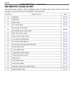
DIAGNOSTIC CODE CHART
After confirming the symptoms, check the diagnosis codes. If a trouble code is output, check the circuit corre-
sponding to that circuit as found in the diagnostic code chart below.
Code No.
Inspection Circuit
Page
12
PRM Signal
13
PRM Signal
14
Ignition Signal
16
ECT Control Signal
21
Main Oxygen Sensor Signal
21
Main Oxygen Sensor Heater Signal
22
Water Temp. Sensor Signal
24
Intake Air Temp. Sensor Signal
25
Air–fuel Ratio Lean Malfunction
26
Air–fuel Ratio Rich Malfunction
27
Sub–oxygen Sensor Signal (California Only)
31
Air Flow Meter Signal
32
Air Flow Meter Signal
41
Throttle Position Sensor Signal
42
Vehicle Speed Sensor Signal
43
Starter Signal
52
Knock Sensor Signal
53
Knock Control Signal
71
EGR System Malfunction (California Only)
51
Switch Condition Signal
TR–18
–
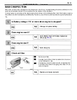
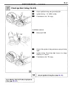
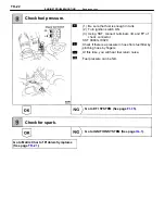
ENGINE TROUBLESHOOTING
Diagnostic Code Chart
Summary of Contents for 2VZ-FE
Page 1: ...ENGINE MECHANICAL EM 1 ENGINE MECHANICAL Description Operation ...
Page 31: ...CYLINDER HEADS COMPONENTS EM 29 ENGINE MECHANICAL Cylinder Heads ...
Page 63: ...CYLINDER BLOCK REMOVAL OF ENGINE EM 61 ENGINE MECHANICAL Cylinder Block ...
Page 64: ...EM 62 ENGINE MECHANICAL Cylinder Block ...
Page 71: ...COMPONENTS EM 69 ENGINE MECHANICAL Cylinder Block ...
Page 106: ...EFI SYSTEM FI 1 ...
Page 107: ...DESCRIPTION FI 2 EFI SYSTEM Description ...
Page 111: ...OPERATION System Circuit FI 4 EFI SYSTEM Operation System Circuit ...
Page 121: ...FUEL SYSTEM Fuel Pump EFI SYSTEM Fuel System Fuel Pump FI 15 ...
Page 141: ...Fuel Tank and Lines COMPONENTS EFI SYSTEM Fuel System Fuel Tank and Lines FI 35 ...
Page 172: ...EXHAUST SYSTEM EXHAUST SYSTEM REPAIR INSTRUCTIONS EX 1 ...
Page 174: ...EMISSION CONTROL SYSTEMS EC 1 ...
Page 186: ...COOLING SYSTEM CO 1 ...
Page 205: ...LUBRICATION SYSTEM LUBRICATION SYSTEM Description Operation LU 1 ...
Page 224: ...IGNITION SYSTEM IG 1 ...
Page 237: ...SERVICE SPECIFICATIONS IG 14 IGNITION SYSTEM ServiceSpecifications ...
Page 238: ...ENGINE TROUBLESHOOTING TR 1 ...


